Use Finder
Glossary Search
Article 2. Form
Part 2A. Introduction
Div. 2A.1. Orientation
Sec. 2A.1.1. Relationship to Zone String
A zone string is composed of the following districts:

The Form District is a separate and independent component of each zone.
Sec. 2A.1.2. How to Use Article 2. (Form)
Identify the Applicable Form District
The first component in a zone string is the Form District applied to a property.
Determine Applicable Form District Standards
Form Districts standards are outlined in Part 2B. (Form Districts). Each Form District page identifies the standards specific to that Form District.
Each standard on a Form District page in Part 2B. (Form Districts) provides a reference to Part 2C. (Form Rules) where the standard is explained in detail. Text in italics below a heading provides a definition of that heading.
![Diagram explaining how to locate and apply form district standards in a Zoning Code. The example highlights the zone string ‘LM2 MU2-5 [RG1-FA]’ and identifies the ‘LM2’ section as the applied form district. The image references Part 2B for Form Districts, showing diagrams of lot parameters and building mass with labeled sections for form categories and standards. It then directs the viewer to Part 2C for Form Rules, where detailed building regulations are listed. Green callout boxes guide users to ‘Find Your Applied Form District’ and ‘Find Your Rules.’](/sites/default/files/styles/large/public/zcode_images/2026.3.0/2A.1.2.1.png.webp?itok=49gv9kRq)
![Diagram explaining how to locate and apply form district standards in a Zoning Code. The example highlights the zone string ‘LM2 MU2-5 [RG1-FA]’ and identifies the ‘LM2’ section as the applied form district. The image references Part 2B for Form Districts, showing diagrams of lot parameters and building mass with labeled sections for form categories and standards. It then directs the viewer to Part 2C for Form Rules, where detailed building regulations are listed. Green callout boxes guide users to ‘Find Your Applied Form District’ and ‘Find Your Rules.’](/sites/default/files/styles/larger/public/zcode_images/2026.3.0/2A.1.2.1.png?itok=xgRU-hFA)
Sec. 2A.1.3. Form District Diagrams
General
Diagrams and illustrations within this Article (Form) are provided to assist users in understanding the intent and requirements of the text. In the event a conflict occurs between the text of this Article (Form) and any illustration or graphic, the text prevails.
Lot Parameter Diagrams
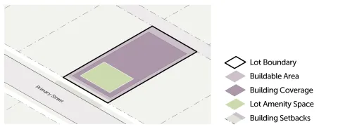
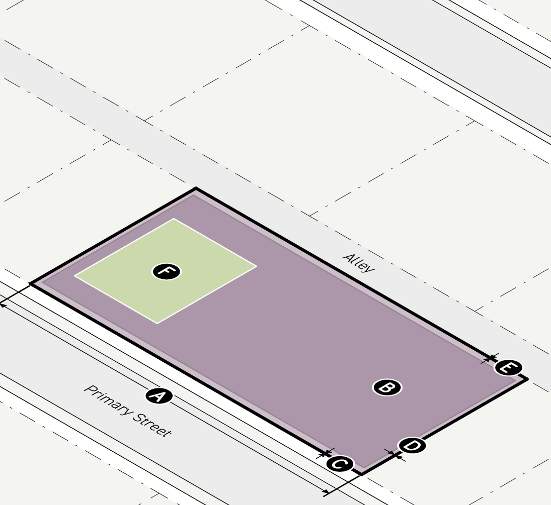
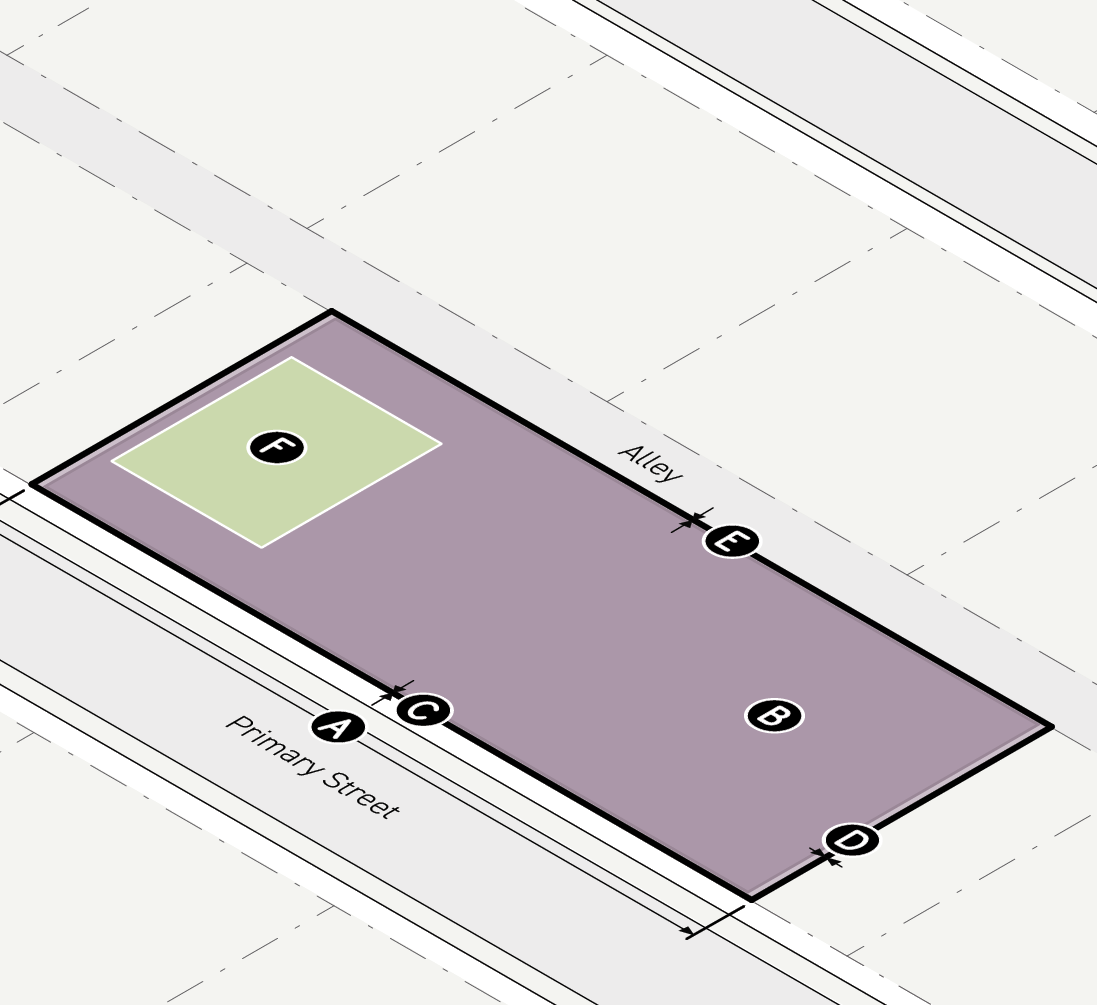
Lot Boundary
This line represents the perimeter of the subject lot, serving as a reference for both lot area and lot width.
Buildable Area
This shape represents the area on a lot where buildings are allowed, reduced by required building setbacks, or the lot boundary when no setback is required.
Building Setbacks
The area between a lot boundary and the minimum required setback, represented with a dotted white line and bounded by the buildable area.
Building Coverage
This shape represents the total building coverage allowed in proportion to the lot area, but does not reflect any requirement as to the location or configuration of any buildings or structures.
Lot Amenity Space
This shape represents the total lot amenity space required in proportion to the lot area, but does not reflect any requirement as to the location or configuration of any amenity space.
Bulk and Mass Diagrams
General
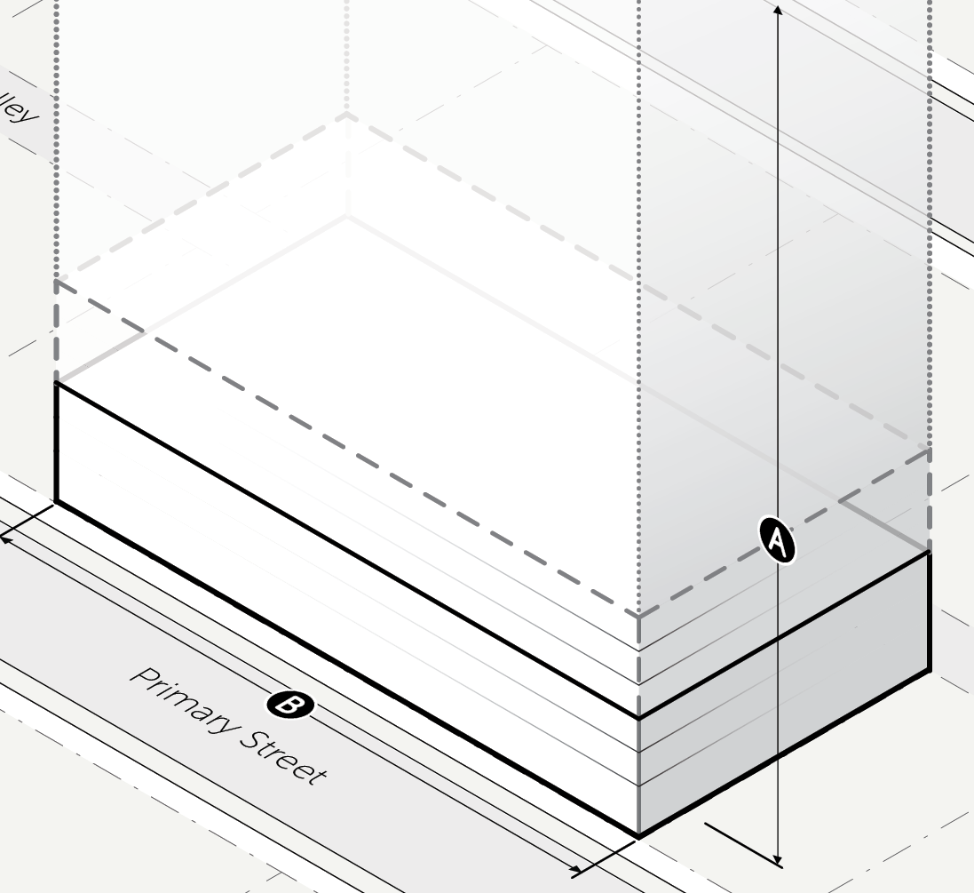
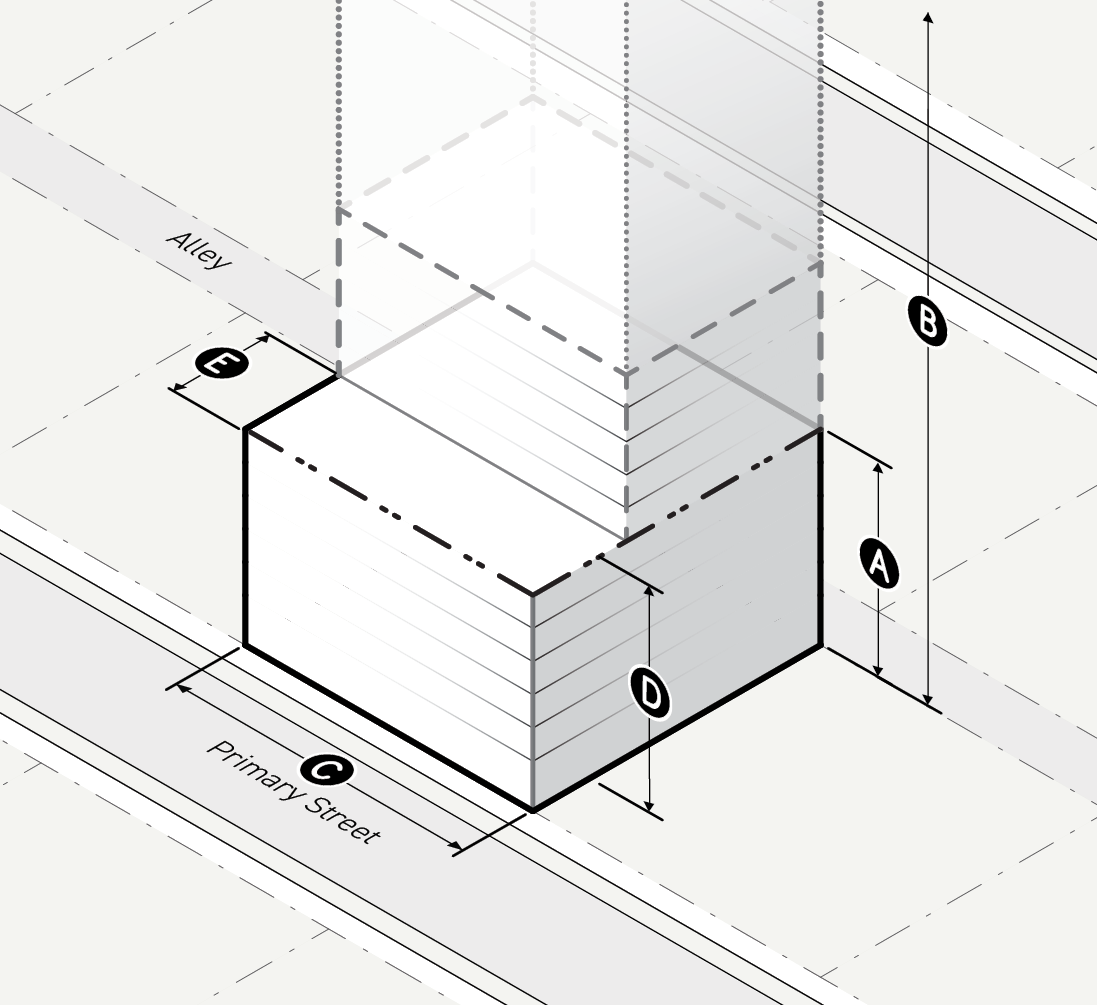
Bulk and mass diagrams represent the volume where a building is allowed to be located by showing the maximum height allowed for the entire buildable area. Except for House, Estate, and Rural Form Districts, the volume does not represent the massing of an allowed building. Other standards, such as maximum building coverage and floor area ratio (FAR), may limit the ability for a building to fill the full volume.
Form Districts (Part 2B.) that include a maximum height standard and those tthat do not include a height limit are represented differently in the bulk and mass diagram.
Districts with a Maximum Height Standard

Maximum Bonus Height
Maximum bonus height represents the maximum number of stories allowed beyond the number of stories allowed by the maximum base height in stories.
Maximum Base Height
Maximum base height represents the number of stories allowed without providing public benefits in trade for additional height according to Article 9. (Public Benefit Systems).
Minimum Height
Minimum height represents the lowest number of stories required.
Districts with no Maximum Height Standard

Unlimited Height
This volume represents the building height allowed, in addition to the likely height of the building based on maximum Base FAR.
Likely Height Based on Bonus FAR
This volume represents the likely building height based on the maximum allowed bonus FAR, in addition to the likely height of the building based on maximum base FAR.
Likely Height Based on Base FAR
This volume represents the likely building height based on the maximum allowed base FAR, in addition to the minimum required height of the building.
Minimum Height
This volume represents the minimum number of stories required.


Sec. 2A.1.4. Form District Naming Convention
There are three different types of naming conventions for Form Districts (Part 2B.). Each Form District name is composed of a variety of components that are specific to that district.
Rural & Estate Form Districts
[Reserved]
House Form Districts
House Form Districts include a range and combination of building coverage, scale, and massing parameters that are intended to produce what is commonly understood as a house. House forms are laid out as detached, or semi-detached, buildings with set-back requirements from the street and lot lines, along with building coverage limitations intended to preserve space for yards and open space. Building widths are narrow, ranging from 50-feet to an upper limit of 100-feet. Building heights are limited by a prescribed number of feet rather than stories, and building scale is further limited by floor area ratio maximums ranging from 0.45 to an upper limit of 1.0. Additional controls are applied to shape upper-story building mass to produce roof forms common on houses.
All Other Form Districts
All other Form District names are composed of three components:
FAR Category
The first component of each Form District name is a floor area ratio (FAR) category. FAR categories group all districts within a range of maximum allowed FAR. FAR categories are organized as follows:
Building Width Category
The second component of each Form District name is a building width category. Building width categories group all districts within a range of maximum allowed building width. Each building width category is organized as follows:
Narrow (25 feet - 75 feet)
Medium (100 feet - 210 feet)
Broad (280 feet - 490 feet)
Full (no building width maximum)
Variation Number
The last component of each Form District is a variation number. All Form Districts are numbered in the order they fall within this Article (Form).
Example Form District
Potential Form District categories are shown below to illustrate the naming convention that would be applied to new Form Districts that may be added to this Article (Form) through future code amendments.


Div. 2A.2. General Rules
Sec. 2A.2.1. Form
This Article (Form) regulates the placement, scale, and intensity of buildings and structures on a lot in order to ensure building forms are compatible with their context and promote projects that support community goals.
Sec. 2A.2.2. Form Applicability
General
All projects filed after the effective date of this Zoning Code (Chapter 1A) shall comply with the Form District standards in this Article (Form), as further specified in the applicability statement of each Section in Part 2C. (Form Rules). Form District standards only apply to the project activities listed in each Section's applicability statement in Part 2C. (Form Rules). For vested rights, see Sec. 1.4.5. (Vested Rights), and for continuance of existing development, see Sec. 1.4.6. (Continuance of Existing Development).
Applicable Components of Lots, Buildings, & Structures
Unless otherwise provided, Form District (Part 2B.) standards apply to all portions of a lot and all buildings and structures on a lot.
Nonconformities
Article 12. (Nonconformities) may provide relief from the requirements of this Article (Form) for existing lots, site improvements, buildings, structures, and uses that conformed to the zoning regulations, at the time they were established, but do not conform to current district standards or use permissions. All project activities shall conform with Form District (Part 2B.) standards unless otherwise specified by Div. 12.2. (Form Exceptions).
Part 2B. Form Districts
Div. 2B.1. Rural Form Districts
[Reserved].
Div. 2B.2. Estate Form Districts
[Reserved].
Div. 2B.3. House Form Districts
[Reserved]
Sec. 2B.3.1. House 1 (H1)
[Reserved]
Sec. 2B.3.2. House 2 (H2)
[Reserved]
Sec. 2B.3.3. House 3 (H3)
A.Lot Parameters |
||
|
|
||
|
1. Lot Size |
||
|
Lot area (min) |
4,000 sf |
|
|
Lot width (min) |
40' |
|
|
2. Coverage |
||
|
A |
Building coverage (max) |
65% |
|
Building setbacks |
||
|
B |
Primary street (min) |
10' |
|
Side street (min) |
5' |
|
|
C |
Side (min) |
3' |
|
D |
Rear (min) |
3' |
|
Alley (min) |
0' |
|
|
Special: All (min) |
0' |
|
|
3. Amenity |
||
|
E |
Lot Amenity space (min) |
15% |
|
Residential amenity space (min) |
10% |
|

B.Bulk and Mass |
||
|
|
||
|
1. FAR & Height |
||
|
Floor area ratio (FAR) (max) |
0.6 |
|
|
A |
Height in feet (max) |
33' |
|
2. Building Mass |
||
|
C |
Building width (max) |
50' |
|
Building break (min) |
6' |
|
|
3. Upper-story Bulk |
||
|
B |
Wall plate height (max) |
22' |

Div. 2B.4. Very Low-Rise Narrow Form Districts
Pursuant to Sec. 2A.1.4. (Form District Naming Convention), each Very Low-Rise Narrow Form District has a maximum FAR ranging from 0.6 to 1.5, and a maximum building width ranging from 25 to 75 feet.
Sec. 2B.4.1. Very Low-Rise Narrow 1 (VN1)
A.Lot Parameters |
||
|
|
||
|
1. Lot Size |
||
|
Lot area (min) |
4,000 sf |
|
|
Lot width (min) |
40' |
|
|
2. Coverage |
||
|
a |
Building coverage (max) |
65% |
|
Building setbacks |
||
|
b |
Primary street (min) |
10' |
|
Side street (min) |
5' |
|
|
c |
Side (min) |
3' |
|
Rear (min) |
3' |
|
|
d |
Alley (min) |
0' |
|
Special: All (min) |
0' |
|
|
3. Amenity |
||
|
E |
Lot amenity space (min) |
15% |
|
Residential amenity space (min) |
10% |
|

B.Bulk and Mass |
||
|
|
||
|
1. FAR & Height |
||
|
Floor area ratio (FAR) |
||
|
Base (max) |
1.0 |
|
|
Bonus (max) |
1.5 |
|
|
A |
Height in stories (max) |
4 |
|
2. Building Mass |
||
|
Building Width (max) |
50' |
|
|
Building break (min) |
6' |
|
|
3. Upper-story Bulk |
||
|
Wall plate height (max) |
34' |
|

Div. 2B.5. Very Low-Rise Medium Form Districts
[Reserved].
Sec. 2B.5.1. Very Low-Rise Medium 1 (VM1)
A.Lot Parameters |
||
|
|
||
|
1. Lot Size |
||
|
Lot area (min) |
None |
|
|
Lot width (min) |
20' |
|
|
2. Coverage |
||
|
a |
Building coverage (max) |
85% |
|
Building setbacks |
||
|
b |
Primary street (min) |
0' |
|
Side street (min) |
0' |
|
|
c |
Side (min) |
0' |
|
Rear (min) |
0' |
|
|
d |
Alley (min) |
0' |
|
Special: All (min) |
15' |
|
|
3. Amenity |
||
|
E |
Lot amenity space (min) |
30% |
|
Residential amenity space (min) |
10% |
|

B.Bulk and Mass |
||
|
|
||
|
1. FAR & Height |
||
|
Floor area ratio (FAR) max |
1.5 |
|
|
A |
Height in feet (max) |
45' |
|
2. Building Mass |
||
|
B |
Building width (max) |
210' |
|
Building break (min) |
15' |
|
|
3. Upper-story Bulk |
||
|
Not applicable |
||

Sec. 2B.5.2. Very Low-Rise Medium 2 (VM2)
A.Lot Parameters |
||
|
|
||
|
1. Lot Size |
||
|
Lot area (min) |
None |
|
|
Lot width (min) |
20' |
|
|
2. Coverage |
||
|
A |
Building coverage (max) |
100% |
|
Building setbacks |
||
|
B |
Primary street (min) |
0' |
|
Side street (min) |
0' |
|
|
C |
Side (min) |
0' |
|
Rear (min) |
0' |
|
|
D |
Alley (min) |
0' |
|
Special: All (min) |
0' |
|
|
3. Amenity |
||
|
E |
Lot amenity space (min) |
15% |
|
Residential amenity space (min) |
10% |
|

B.Bulk and Mass |
||
|
|
||
|
1. FAR & Height |
||
|
Floor area ratio (FAR) max |
1.5 |
|
|
A |
Height in feet (max) |
65' |
|
2. Building Mass |
||
|
B |
Building width (max) |
210' |
|
Building break (min) |
15' |
|
|
3. Upper-story Bulk |
||
|
Not applicable |
||

Div. 2B.6. Very Low-Rise Broad Form Districts
[Reserved].
Div. 2B.7. Very Low-Rise Full Form Districts
Pursuant to Sec. 2A.1.4. (Form District Naming Convention), each Very Low-Rise Full Form District has a maximum FAR ranging from 0.6 to 1.5, and no maximum building width.
Sec. 2B.7.1. Very Low-Rise Full 1 (VF1)
A.Lot Parameters |
||
|
|
||
|
1. Lot Size |
||
|
Lot area (min) |
None |
|
|
A |
Lot width (min) |
20' |
|
2. Coverage |
||
|
B |
Building coverage (max) |
25% |
|
Building setbacks |
||
|
C |
Primary street (min) |
0' |
|
Side street (min) |
0' |
|
|
D |
Side (min) |
0' |
|
Rear (min) |
0' |
|
|
E |
Alley (min) |
0' |
|
Special: River (min) |
10' |
|
|
Special: Other (min) |
0' |
|
|
3. Amenity |
||
|
Not applicable |
||

B.Bulk and Mass |
||
|
|
||
|
1. FAR & Height |
||
|
Floor area ratio (FAR) (max) |
1.5 |
|
|
A |
Height (max) |
None |
|
2. Building Mass |
||
|
Not applicable |
||
|
3. Upper-story Bulk |
||
|
Not applicable |
||

Sec. 2B.7.2. Very Low-Rise Full 2 (VF2)
A.Lot Parameters |
||
|
|
||
|
1. Lot Size |
||
|
Lot area (min) |
None |
|
|
Lot width (min) |
20' |
|
|
2. Coverage |
||
|
a |
Building coverage (max) |
100% |
|
Building setbacks |
||
|
b |
Primary street (min) |
0' |
|
Side street (min) |
0' |
|
|
c |
Side (min) |
0' |
|
Rear (min) |
0' |
|
|
d |
Alley (min) |
0' |
|
Special: All (min) |
0' |
|
|
3. Amenity |
||
|
Not applicable |
||

B.Bulk and Mass |
||
|
|
||
|
1. FAR & Height |
||
|
Floor area ratio (FAR) (max) |
1.5 |
|
|
A |
Height (max) |
None |
|
2. Building Mass |
||
|
Not applicable |
||
|
3. Upper-story Bulk |
||
|
Not applicable |
||

Div. 2B.8. Low-Rise Narrow Form Districts
Pursuant to Sec. 2A.1.4. (Form District Naming Convention), each Low-Rise Narrow Form District has a maximum FAR ranging from 1.6 to 4.0, and a maximum building width ranging from 25 to 75 feet.
Sec. 2B.8.1. Low-Rise Narrow 1 (LN1)
A.Lot Parameters |
||
|
|
||
|
1. Lot Size |
||
|
A |
Lot area (min) |
2,500 sf |
|
B |
Lot width (min) |
25' |
|
2. Coverage |
||
|
C |
Building coverage (max) |
80% |
|
Building setbacks |
||
|
D |
Primary street (min) |
5' |
|
Side street (min) |
0' |
|
|
E |
Side (min) |
0' |
|
Rear (min) |
0' |
|
|
F |
Alley (min) |
0' |
|
Special: All (min) |
0' |
|
|
3. Amenity |
||
|
G |
Lot amenity space (min) |
25% |
|
Residential amenity space (min) |
10% |
|

B.Bulk and Mass |
||
|
|
||
|
1. FAR & Height |
||
|
Floor area ratio (FAR) |
||
|
Base (max) |
1.5 |
|
|
Bonus (max) |
3.0 |
|
|
Height in stories |
||
|
A |
Base (max) |
3 |
|
B |
Bonus (max) |
6 |
|
2. Building Mass |
||
|
C |
Building width (max) |
75' |
|
Building break (min) |
6' |
|
|
3. Upper-story Bulk |
||
|
Street step-back |
||
|
D |
Stories without step-back (max) |
4 |
|
E |
Primary street step-back depth (min) |
10' |
|
Side street step-back depth (min) |
10' |
|
|
F |
Height transition |
Required |

Div. 2B.9. Low-Rise Medium Form Districts
Pursuant to Sec. 2A.1.4. (Form District Naming Convention), each Low-Rise Medium Form District has a maximum FAR ranging from 1.6 to 4.0, and a maximum building width ranging from 100 to 210 feet.
Sec. 2B.9.1. Low-Rise Medium 1 (LM1)
A.Lot Parameters |
||
|
|
||
|
1. Lot Size |
||
|
Lot area (min) |
None |
|
|
A |
Lot width (min) |
25' |
|
2. Coverage |
||
|
b |
Building coverage (max) |
100% |
|
Building setbacks |
||
|
c |
Primary street (min) |
0' |
|
Side street (min) |
0' |
|
|
d |
Side (min) |
0' |
|
Rear (min) |
0' |
|
|
e |
Alley (min) |
0' |
|
Special: All (min) |
0' |
|
|
3. Amenity |
||
|
f |
Lot amenity space (min) |
15% |
|
Residential amenity space (min) |
10% |
|

B.Bulk and Mass |
||
|
|
||
|
1. FAR & Height |
||
|
Floor area ratio (FAR) |
||
|
Base (max) |
1.5 |
|
|
Bonus (max) |
3.0 |
|
|
Height in stories |
||
|
A |
Base (max) |
8 |
|
B |
Bonus (max) |
10 |
|
2. Building Mass |
||
|
C |
Building width (max) |
160' |
|
Building break (min) |
15' |
|
|
3. Upper-story Bulk |
||
|
Not applicable |
||

Sec. 2B.9.2. Low-Rise Medium 2 (LM2)
A.Lot Parameters |
||
|
|
||
|
1. Lot Size |
||
|
A |
Lot area (min) |
2,500 sf |
|
B |
Lot width (min) |
25' |
|
2. Coverage |
||
|
C |
Building coverage (max) |
90% |
|
Building setbacks |
||
|
D |
Primary street (min) |
0' |
|
Side street (min) |
0' |
|
|
E |
Side (min) |
0' |
|
Rear (min) |
0' |
|
|
F |
Alley (min) |
0' |
|
Special: All (min) |
0' |
|
|
3. Amenity |
||
|
G |
Lot amenity space (min) |
25% |
|
Residential amenity space (min) |
10% |
|

B.Bulk and Mass |
||
|
|
||
|
1. FAR & Height |
||
|
Floor area ratio (FAR) |
||
|
Base (max) |
1.5 |
|
|
Bonus (max) |
3.0 |
|
|
Height in stories |
||
|
A |
Base (max) |
3 |
|
B |
Bonus (max) |
6 |
|
2. Building Mass |
||
|
C |
Building width (max) |
100' |
|
Building break (min) |
15' |
|
|
3. Upper-story Bulk |
||
|
Not applicable |
||

Sec. 2B.9.3. Low-Rise Medium 3 (LM3)
A.Lot Parameters |
||
|
|
||
|
1. Lot Size |
||
|
Lot area (min) |
None |
|
|
Lot width (min) |
20' |
|
|
2. Coverage |
||
|
A |
Building coverage (max) |
100% |
|
B |
Building setbacks |
|
|
Primary street (min) |
0' |
|
|
Side street (min) |
0' |
|
|
C |
Side (min) |
0' |
|
Rear (min) |
10' |
|
|
D |
Alley (min) |
0' |
|
Special: All (min) |
0' |
|
|
3. Amenity |
||
|
E |
Lot amenity space (min) |
15% |
|
Residential amenity space (min) |
10% |
|

B.Bulk and Mass |
||
|
|
||
|
1. FAR & Height |
||
|
Floor area ratio (FAR) |
||
|
Base (max) |
1.5 |
|
|
Bonus (max) |
2.5 |
|
|
Height in stories |
||
|
A |
Base (max) |
2 |
|
B |
Bonus (max) |
4 |
|
2. Building Mass |
||
|
E |
Building width (max) |
140' |
|
Building break (min) |
15' |
|
|
3. Upper-story Bulk |
||
|
Street step-back |
||
|
C |
Stories without step-back (max) |
2 |
|
D |
Primary street step-back depth (min) |
10' |
|
Side street step-back depth (min) |
None |
|

Sec. 2B.9.4. Low-Rise Medium 4 (LM4)
A.Lot Parameters |
||
|
|
||
|
1. Lot Size |
||
|
Lot area (min) |
None |
|
|
Lot width (min) |
20' |
|
|
2. Coverage |
||
|
A |
Building coverage (max) |
100% |
|
Building setbacks |
||
|
b |
Primary street (min) |
0' |
|
Side street (min) |
0' |
|
|
C |
Side (min) |
0' |
|
Rear (min) |
0' |
|
|
D |
Alley (min) |
0' |
|
Special: All (min) |
10' |
|
|
3. Amenity |
||
|
E |
Lot amenity space (min) |
20% |
|
Residential amenity space (min) |
10% |
|

B.Bulk and Mass |
||
|
|
||
|
1. FAR & Height |
||
|
Floor area ratio (FAR) |
||
|
Base (max) |
1.5 |
|
|
Bonus (max) |
3.0 |
|
|
A |
Height (max) |
None |
|
2. Building Mass |
||
|
B |
Building width (max) |
210' |
|
Building break (min) |
15' |
|
|
3. Upper-story Bulk |
||
|
Height transition |
Required |
|

Sec. 2B.9.5. Low-Rise Medium 5 (LM5)
A.Lot Parameters |
||
|
|
||
|
1. Lot Size |
||
|
Lot area (min) |
None |
|
|
Lot width (min) |
20' |
|
|
2. Coverage |
||
|
A |
Building coverage (max) |
100% |
|
Building setbacks |
||
|
B |
Primary street (min) |
0' |
|
Side street (min) |
0' |
|
|
C |
Side (min) |
0' |
|
Rear (min) |
0' |
|
|
D |
Alley (min) |
0' |
|
Special: All (min) |
0' |
|
|
3. Amenity |
||
|
E |
Lot amenity space (min) |
20% |
|
Residential amenity space (min) |
10% |
|

B.Bulk and Mass |
||
|
|
||
|
1. FAR & Height |
||
|
Floor area ratio (FAR) |
||
|
Base (max) |
2.0 |
|
|
Bonus (max) |
4.0 |
|
|
Height in stories |
||
|
A |
Base (max) |
7 |
|
B |
Bonus (max) |
11 |
|
2. Building Mass |
||
|
C |
Building width (max) |
210' |
|
Building break (min) |
15' |
|
|
3. Upper-story Bulk |
||
|
Height transition |
Required |
|

Sec. 2B.9.6. Low-Rise Medium 6 (LM6)
A.Lot Parameters |
||
|
|
||
|
1. Lot Size |
||
|
Lot area (min) |
None |
|
|
Lot width (min) |
20' |
|
|
2. Coverage |
||
|
A |
Building coverage (max) |
100% |
|
Building setbacks |
||
|
B |
Primary street (min) |
0' |
|
Side street (min) |
0' |
|
|
C |
Side (min) |
0' |
|
Rear (min) |
0' |
|
|
D |
Alley (min) |
0' |
|
Special: All (min) |
10' |
|
|
3. Amenity |
||
|
E |
Lot amenity space (min) |
20% |
|
Residential amenity space (min) |
10% |
|

B.Bulk and Mass |
||
|
|
||
|
1. FAR & Height |
||
|
Floor area ratio (FAR) |
||
|
Base (max) |
1.5 |
|
|
Bonus (max) |
4.0 |
|
|
A |
Height (max) |
None |
|
2. Building Mass |
||
|
b |
Building width (max) |
140' |
|
Building break (min) |
15' |
|
|
3. Upper-story Bulk |
||
|
Height transition |
Required |
|

Sec. 2B.9.7. Low-Rise Medium 7 (LM7)
A.Lot Parameters |
||
|
|
||
|
1. Lot Size |
||
|
Lot area (min) |
None |
|
|
Lot width (min) |
20' |
|
|
2. Coverage |
||
|
A |
Building coverage (max) |
100% |
|
Building setbacks |
||
|
B |
Primary street (min) |
0' |
|
Side street (min) |
0' |
|
|
C |
Side (min) |
0' |
|
Rear (min) |
0' |
|
|
Alley (min) |
0' |
|
|
D |
Special: All (min) |
15' |
|
3. Amenity |
||
|
E |
Lot amenity space (min) |
20% |
|
Residential amenity space (min) |
10% |
|
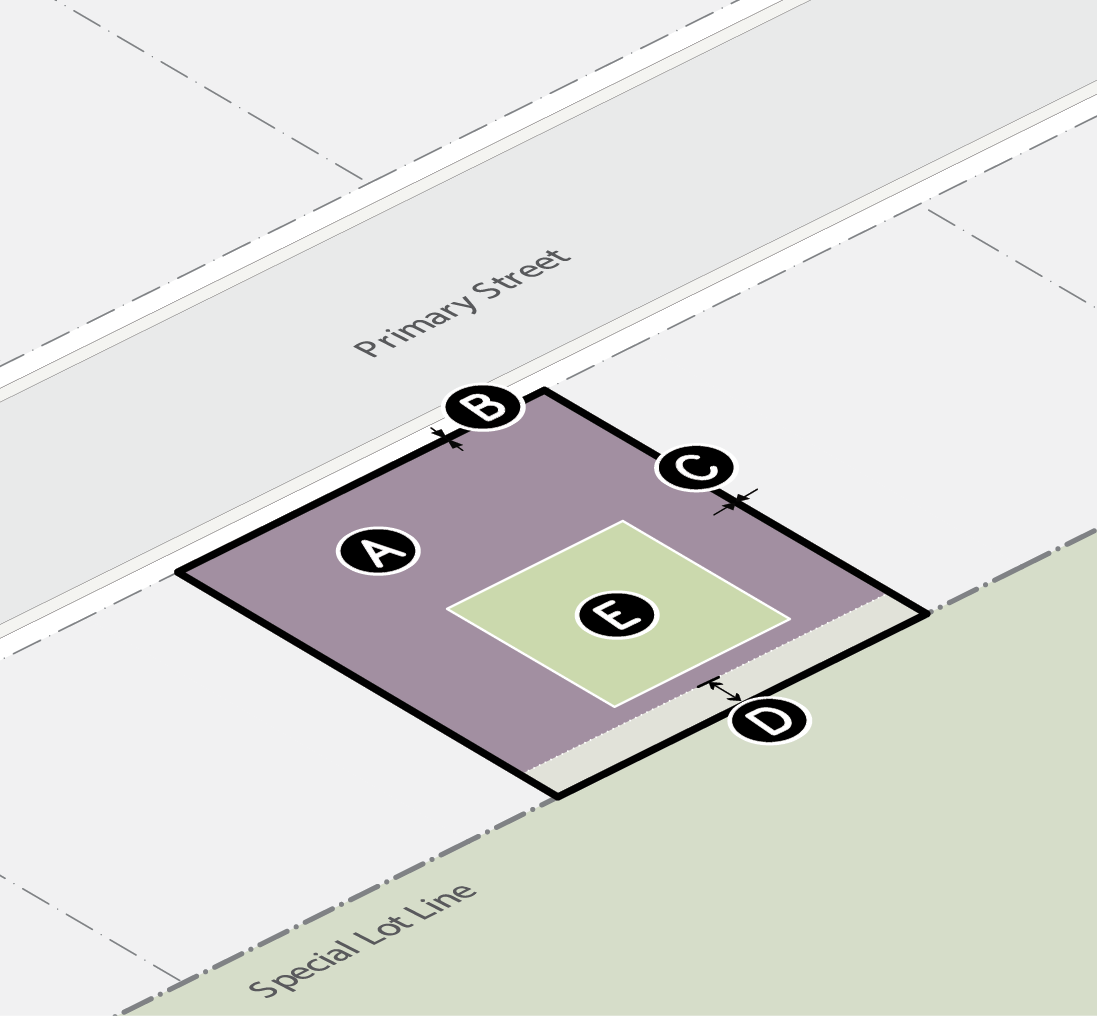
B.Bulk and Mass |
||
|
|
||
|
1. FAR & Height |
||
|
Floor area ratio (FAR) (max) |
||
|
Base (max) |
1.5 |
|
|
Bonus (max) |
4.0 |
|
|
A |
Height (max) |
None |
|
2. Building Mass |
||
|
b |
Building width (max) |
140' |
|
Building break (min) |
15' |
|
|
3. Upper-story Bulk |
||
|
C |
Height transition |
Required |
|
Applicable lot line: |
Special |
|

Div. 2B.10. Low-Rise Broad Form Districts
Pursuant to Sec. 2A.1.4. (Form District Naming Convention), each Low-Rise Broad Form District has a maximum FAR ranging from 1.6 to 4.0, and a maximum building width ranging from 280 to 490 feet.
Sec. 2B.10.1. Low-Rise Broad 1 (LB1)
A.Lot Parameters |
||
|
|
||
|
1. Lot Size |
||
|
Lot area (min) |
None |
|
|
A |
Lot width (min) |
25' |
|
2. Coverage |
||
|
B |
Building coverage (max) |
90% |
|
Building setbacks |
||
|
C |
Primary street (min) |
0' |
|
Side street (min) |
0' |
|
|
D |
Side (min) |
0' |
|
Rear (min) |
0' |
|
|
E |
Alley (min) |
0' |
|
Special: All (min) |
0' |
|
|
3. Amenity |
||
|
F |
Lot amenity space (min) |
15% |
|
Residential amenity space (min) |
10% |
|

B.Bulk and Mass |
||
|
|
||
|
1. FAR & Height |
||
|
Floor area ratio (FAR) |
3.0 |
|
|
A |
Height (max) |
None |
|
2. Building Mass |
||
|
B |
Building width (max) |
350' |
|
Building break (min) |
25' |
|
|
3. Upper-story Bulk |
||
|
Not applicable |
||

Sec. 2B.10.2. Low-Rise Broad 2 (LB2)
A.Lot Parameters |
||
|
|
||
|
1. Lot Size |
||
|
Lot area (min) |
None |
|
|
A |
Lot width (min) |
25' |
|
2. Coverage |
||
|
B |
Building coverage (max) |
90% |
|
Building setbacks |
||
|
C |
Primary street (min) |
0' |
|
Side street (min) |
0' |
|
|
D |
Side (min) |
0' |
|
Rear (min) |
0' |
|
|
E |
Alley (min) |
0' |
|
Special: River (min) |
10' |
|
|
Special: Other (min) |
0' |
|
|
3. Amenity |
||
|
F |
Lot amenity space (min) |
15% |
|
Residential amenity space (min) |
10% |
|

B.Bulk and Mass |
||
|
|
||
|
1. FAR & Height |
||
|
Floor area ratio (FAR) |
||
|
Base (max) |
1.5 |
|
|
Bonus (max) |
3.0 |
|
|
A |
Height in stories (max) |
5 |
|
2. Building Mass |
||
|
B |
Building width (max) |
280' |
|
Building break (min) |
25' |
|
|
3. Upper-story Bulk |
||
|
Not applicable |
||

Div. 2B.11. Low-Rise Full Form Districts
Pursuant to Sec. 2A.1.4. (Form District Naming Convention), each Low-Rise Full Form District has a maximum FAR ranging from 1.6 to 4.0, and no maximum building width.
Sec. 2B.11.1. Low-Rise Full 1 (LF1)
A.Lot Parameters |
||
|
|
||
|
1. Lot Size |
||
|
Lot area (min) |
None |
|
|
A |
Lot width (min) |
20' |
|
2. Coverage |
||
|
B |
Building coverage (max) |
100% |
|
Building setbacks |
||
|
C |
Primary street (min) |
0' |
|
Side street (min) |
0' |
|
|
D |
Side (min) |
0' |
|
Rear (min) |
0' |
|
|
E |
Alley (min) |
0' |
|
Special: All (min) |
0' |
|
|
3. Amenity |
||
|
Not applicable |
||

B.Bulk and Mass |
||
|
|
||
|
1. FAR & Height |
||
|
Floor area ratio (FAR) (max) |
3.0 |
|
|
a |
Height (max) |
None |
|
City Hall Height Restriction |
Required |
|
|
2. Building Mass |
||
|
Not applicable |
||
|
3. Upper-story Bulk |
||
|
Not applicable |
||

Sec. 2B.11.2. Low-Rise Full 2 (LF2)
A.Lot Parameters |
||
|
|
||
|
1. Lot Size |
||
|
Lot area (min) |
None |
|
|
A |
Lot width (min) |
20' |
|
2. Coverage |
||
|
B |
Building coverage (max) |
100% |
|
Building setbacks |
||
|
C |
Primary street (min) |
0' |
|
Side street (min) |
0' |
|
|
D |
Side (min) |
0' |
|
Rear (min) |
0' |
|
|
E |
Alley (min) |
0' |
|
Special: River (min) |
10' |
|
|
Special: Other (min) |
0' |
|
|
3. Amenity |
||
|
Not applicable |
||

B.Bulk and Mass |
||
|
|
||
|
1. FAR & Height |
||
|
Floor area ratio (FAR) (max) |
3.0 |
|
|
A |
Height (max) |
None |
|
2. Building Mass |
||
|
Not applicable |
||
|
3. Upper-story Bulk |
||
|
Not applicable |
||
Div. 2B.12. Mid-Rise Narrow Form Districts
Pursuant to Sec. 2A.1.4. (Form District Naming Convention), each Mid-Rise Narrow Form District has a maximum FAR ranging from 4.1 to 6.0, and a maximum building width ranging from 25 to 75 feet.
Sec. 2B.12.1. Mid-Rise Narrow 1 (MN1)
A.Lot Parameters |
||
|
|
||
|
1. Lot Size |
||
|
Lot area (min) |
None |
|
|
A |
Lot width (min) |
25' |
|
2. Coverage |
||
|
B |
Building coverage (max) |
100% |
|
Building setbacks |
||
|
C |
Primary street (min) |
0' |
|
Side street (min) |
0' |
|
|
D |
Side (min) |
0' |
|
Rear (min) |
0' |
|
|
E |
Alley (min) |
0' |
|
Special: Alley (min) |
0' |
|
|
Special: Other (min) |
0' |
|
|
3. Amenity |
||
|
F |
Lot amenity space (min) |
10% |
|
Residential amenity space (min) |
10% |
|

B.Bulk and Mass |
||
|
|
||
|
1. FAR & Height |
||
|
Floor area ratio (FAR) |
||
|
Base (max) |
3.0 |
|
|
Bonus (max) |
6.0 |
|
|
Height in stories |
||
|
A |
Base (max) |
3 |
|
B |
Bonus (max) |
5 |
|
2. Building Mass |
||
|
C |
Building width (max) |
75' |
|
Building break (min) |
6' |
|
|
3. Upper-story Bulk |
||
|
Not applicable |
||

Div. 2B.13. Mid-Rise Medium Form Districts
Pursuant to Sec. 2A.1.4. (Form District Naming Convention), each Mid-Rise Medium Form District has a maximum FAR ranging from 4.1 to 6.0, and a maximum building width ranging from 100 to 210 feet.
Sec. 2B.13.1. Mid-Rise Medium 1 (MM1)
A.Lot Parameters |
||
|
|
||
|
1. Lot Size |
||
|
Lot area (min) |
None |
|
|
A |
Lot width (min) |
25' |
|
2. Coverage |
||
|
B |
Building coverage (max) |
90% |
|
Building setbacks |
||
|
C |
Primary street (min) |
0' |
|
Side street (min) |
0' |
|
|
D |
Side (min) |
0' |
|
Rear (min) |
0' |
|
|
E |
Alley (min) |
0' |
|
Special: River (min) |
10' |
|
|
Special: Other (min) |
0' |
|
|
3. Amenity |
||
|
F |
Lot amenity space (min) |
15% |
|
Residential amenity space (min) |
10% |
|

B.Bulk and Mass |
||
|
|
||
|
1. FAR & Height |
||
|
Floor area ratio (FAR) |
||
|
Base (max) |
1.5 |
|
|
Bonus (max) |
4.5 |
|
|
Height in stories |
||
|
A |
Base (max) |
15 |
|
B |
Bonus (max) |
18 |
|
2. Building Mass |
||
|
C |
Building width (max) |
160' |
|
Building break (min) |
15' |
|
|
3. Upper-story Bulk |
||
|
Not applicable |
||

Div. 2B.14. Mid-Rise Broad Form Districts
Pursuant to Sec. 2A.1.4. (Form District Naming Convention), each Mid-Rise Broad Form District has a maximum FAR ranging from 4.1 to 6.0, and a maximum building width ranging from 280 to 490 feet.
Sec. 2B.14.1. Mid-Rise Broad 1 (MB1)
A.Lot Parameters |
||
|
|
||
|
1. Lot Size |
||
|
Lot area (min) |
None |
|
|
A |
Lot width (min) |
25' |
|
2. Coverage |
||
|
B |
Building coverage (max) |
90% |
|
Building setbacks |
||
|
C |
Primary street (min) |
0' |
|
Side street (min) |
0' |
|
|
D |
Side (min) |
0' |
|
Rear (min) |
0' |
|
|
E |
Alley (min) |
0' |
|
Special: All (min) |
0' |
|
|
3. Amenity |
||
|
F |
Lot amenity space (min) |
15% |
|
Residential amenity space (min) |
10% |
|

B.Bulk and Mass |
||
|
|
||
|
1. FAR & Height |
||
|
Floor area ratio (FAR) |
||
|
Base (max) |
1.5 |
|
|
Bonus (max) |
6.0 |
|
|
Height in stories |
||
|
A |
Minimum (Bonus) |
10 |
|
b |
Maximum |
None |
|
2. Building Mass |
||
|
c |
Building width (max) |
280' |
|
Building break (min) |
25' |
|
|
3. Upper-story Bulk |
||
|
Not applicable |
||

Sec. 2B.14.2. Mid-Rise Broad 2 (MB2)
A.Lot Parameters |
||
|
|
||
|
1. Lot Size |
||
|
Lot area (min) |
None |
|
|
A |
Lot width (min) |
25' |
|
2. Coverage |
||
|
B |
Building coverage (max) |
90% |
|
Building setbacks |
||
|
C |
Primary street (min) |
0' |
|
Side street (min) |
0' |
|
|
D |
Side (min) |
0' |
|
Rear (min) |
0' |
|
|
E |
Alley (min) |
0' |
|
Special: All (min) |
0' |
|
|
3. Amenity |
||
|
F |
Lot amenity space (min) |
15% |
|
Residential amenity space (min) |
10% |
|
B.Bulk and Mass |
||
|
|
||
|
1. FAR & Height |
||
|
Floor area ratio (FAR) |
||
|
Base (max) |
3.0 |
|
|
Bonus (max) |
6.0 |
|
|
A |
Height (max) |
None |
|
2. Building Mass |
||
|
B |
Building width (max) |
280' |
|
Building break (min) |
25' |
|
|
3. Upper-story Bulk |
||
|
Not applicable |
||
Div. 2B.15. Mid-Rise Full Form Districts
Pursuant to Sec. 2A.1.4. (Form District Naming Convention), each Mid-Rise Full Form District has a maximum FAR ranging from 4.1 to 6.0, and no maximum building width.
[Reserved]
Div. 2B.16. Moderate-Rise Medium Form Districts
Pursuant to Sec. 2A.1.4. (Form District Naming Convention), each Moderate-Rise Medium Form District has a maximum FAR ranging from 6.1 to 8.5, and a maximum building width ranging from 100 to 210 feet.
Sec. 2B.16.1. Moderate-Rise Medium 1 (DM1)
A.Lot Parameters |
||
|
|
||
|
1. Lot Size |
||
|
Lot area (min) |
None |
|
|
A |
Lot width (min) |
25' |
|
2. Coverage |
||
|
B |
Building coverage (max) |
90% |
|
Building setbacks |
||
|
C |
Primary street (min) |
0' |
|
Side street (min) |
0' |
|
|
D |
Side (min) |
0' |
|
Rear (min) |
0' |
|
|
E |
Alley (min) |
0' |
|
Special: Alley (min) |
0' |
|
|
Special: Other (min) |
0' |
|
|
3. Amenity |
||
|
F |
Lot amenity space (min) |
15% |
|
Residential amenity space (min) |
10% |
|

B.Bulk and Mass |
||
|
|
||
|
1. FAR & Height |
||
|
Floor area ratio (FAR) |
||
|
Base (max) |
3.0 |
|
|
Bonus (max) |
8.0 |
|
|
A |
Height (max) |
None |
|
2. Building Mass |
||
|
B |
Building width (max) |
210' |
|
Building break (min) |
15' |
|
|
3. Upper-story Bulk |
||
|
Not applicable |
||

Sec. 2B.16.2. Moderate-Rise Medium 2 (DM2)
A.Lot Parameters |
||
|
|
||
|
1. Lot Size |
||
|
Lot area (min) |
None |
|
|
A |
Lot width (min) |
25' |
|
2. Coverage |
||
|
B |
Building coverage (max) |
90% |
|
Building setbacks |
||
|
C |
Primary street (min) |
0' |
|
Side street (min) |
0' |
|
|
D |
Side (min) |
0' |
|
Rear (min) |
0' |
|
|
E |
Alley (min) |
0' |
|
Special: All (min) |
0' |
|
|
3. Amenity |
||
|
F |
Lot amenity space (min) |
15% |
|
Residential amenity space (min) |
10% |
|

B.Bulk and Mass |
||
|
|
||
|
1. FAR & Height |
||
|
Floor area ratio (FAR) |
||
|
Base (max) |
3.0 |
|
|
Bonus (max) |
8.5 |
|
|
A |
Height (max) |
None |
|
2. Building Mass |
||
|
B |
Building width (max) |
160' |
|
Building break (min) |
15' |
|
|
3. Upper-story Bulk |
||
|
Not applicable |
||

Sec. 2B.16.3. Moderate-Rise Medium 3 (DM3)
A.Lot Parameters |
||
|
|
||
|
1. Lot Size |
||
|
Lot area (min) |
None |
|
|
A |
Lot width (min) |
25' |
|
2. Coverage |
||
|
B |
Building coverage (max) |
100% |
|
Building setbacks |
||
|
C |
Primary street (min) |
0' |
|
Side street (min) |
0' |
|
|
D |
Side (min) |
0' |
|
Rear (min) |
0' |
|
|
E |
Alley (min) |
0' |
|
Special: All (min) |
0' |
|
|
3. Amenity |
||
|
F |
Lot amenity space (min) |
10% |
|
Residential amenity space (min) |
10% |
|

B.Bulk and Mass |
||
|
|
||
|
1. FAR & Height |
||
|
Floor area ratio (FAR) |
||
|
Base (max) |
3.0 |
|
|
Bonus (max) |
8.5 |
|
|
Height in stories |
||
|
A |
Minimum |
3 |
|
B |
Maximum |
None |
|
2. Building Mass |
||
|
C |
Building width (max) |
160' |
|
Building break (min) |
15' |
|
|
3. Upper-story Bulk |
||
|
Street step-back |
||
|
D |
Stories without step-back (min/max) |
2/12 |
|
E |
Primary street step-back depth (min) |
30' |
|
Side street step-back depth (min) |
30' |
|

Sec. 2B.16.4. Moderate-Rise Medium 4 (DM4)
A.Lot Parameters |
||
|
|
||
|
1. Lot Size |
||
|
Lot area (min) |
None |
|
|
A |
Lot width (min) |
25' |
|
2. Coverage |
||
|
B |
Building coverage (max) |
100% |
|
Building setbacks |
||
|
C |
Primary street (min) |
0' |
|
Side street (min) |
0' |
|
|
D |
Side (min) |
0' |
|
Rear (min) |
0' |
|
|
E |
Alley (min) |
0' |
|
Special: All (min) |
0' |
|
|
3. Amenity |
||
|
F |
Lot amenity space (min) |
10% |
|
Residential amenity space (min) |
10% |
|

B.Bulk and Mass |
||
|
|
||
|
1. FAR & Height |
||
|
Floor area ratio (FAR) |
||
|
Base (max) |
6.0 |
|
|
Bonus (max) |
8.5 |
|
|
Height in stories |
||
|
a |
Minimum |
6 |
|
b |
Maximum |
None |
|
2. Building Mass |
||
|
C |
Building width (max) |
160' |
|
Building break (min) |
15' |
|
|
3. Upper-story Bulk |
||
|
Street step-back |
||
|
D |
Stories without step-back (min/max) |
2/12 |
|
E |
Primary street step-back depth (min) |
30' |
|
Side street step-back depth (min) |
30' |
|
Sec. 2B.16.5. Moderate-Rise Medium 5 (DM5)
A.Lot Parameters |
||

|
||
|
1. Lot Size |
||
|
Lot area (min) |
None |
|
|
A |
Lot width (min) |
25' |
|
2. Coverage |
||
|
B |
Building coverage (max) |
100% |
|
Building setbacks |
||
|
C |
Primary street (min) |
0' |
|
Side street (min) |
0' |
|
|
D |
Side (min) |
0' |
|
Rear (min) |
0' |
|
|
E |
Alley (min) |
0' |
|
Special: All (min) |
0' |
|
|
3. Amenity |
||
|
F |
Lot amenity space (min) |
10% |
|
Residential amenity space (min) |
10% |
|
B.Bulk and Mass |
||
|
|
||
|
1. FAR & Height |
||
|
Floor area ratio (FAR) |
||
|
Base (max) |
6.0 |
|
|
Bonus (max) |
8.5 |
|
|
A |
Height (max) |
None |
|
2. Building Mass |
||
|
B |
Building width (max) |
160' |
|
Building break (min) |
15' |
|
|
3. Upper-story Bulk |
||
|
Street step-back |
||
|
C |
Stories without step-back (min/max) |
2/5 |
|
D |
Primary street step-back depth (min) |
10' |
|
Side street step-back depth (min) |
10' |
|

Div. 2B.17. Moderate-Rise Broad Form Districts
Pursuant to Sec. 2A.1.4. (Form District Naming Convention), each Moderate-Rise Broad Form District has a maximum FAR ranging from 6.1 to 8.5, and a maximum building width ranging from 280 to 490 feet.
[Reserved]
Div. 2B.18. Moderate-Rise Full Form Districts
Pursuant to Sec. 2A.1.4. (Form District Naming Convention), each Moderate-Rise Full Form District has a maximum FAR ranging from 6.1 to 8.5, and no maximum building width.
Sec. 2B.18.1. Moderate-Rise Full 1 (DF1)
A.Lot Parameters |
||
|
|
||
|
1. Lot Size |
||
|
Lot area (min) |
None |
|
|
A |
Lot width (min) |
25' |
|
2. Coverage |
||
|
B |
Building coverage (max) |
95% |
|
Building setbacks |
||
|
C |
Primary street (min) |
0' |
|
Side street (min) |
0' |
|
|
D |
Side (min) |
0' |
|
Rear (min) |
0' |
|
|
E |
Alley (min) |
0' |
|
Special: All (min) |
0' |
|
|
3. Amenity |
||
|
F |
Lot amenity space (min) |
10% |
|
Residential amenity space (min) |
10% |
|
B.Bulk and Mass |
||
|
|
||
|
1. FAR & Height |
||
|
Floor area ratio (FAR) (max) |
6.5 |
|
|
a |
Height (max) |
None |
|
City Hall Height Restriction |
Required |
|
|
2. Building Mass |
||
|
Not applicable |
||
|
3. Upper-story Bulk |
||
|
Not applicable |
||

Div. 2B.19. High-Rise Medium Form Districts
Pursuant to Sec. 2A.1.4. (Form District Naming Convention), each High-Rise Medium Form District has a maximum FAR ranging from 8.6 to 13.0, and a maximum building width ranging from 100 to 210 feet.
Sec. 2B.19.1. High-Rise Medium 1 (HM1)
A.Lot Parameters |
||
|
|
||
|
1. Lot Size |
||
|
Lot area (min) |
None |
|
|
A |
Lot width (min) |
25' |
|
2. Coverage |
||
|
B |
Building coverage (max) |
100% |
|
Building setbacks |
||
|
C |
Primary street (min) |
0' |
|
Side street (min) |
0' |
|
|
D |
Side (min) |
0' |
|
Rear (min) |
0' |
|
|
E |
Alley (min) |
0' |
|
Special: All (min) |
0' |
|
|
3. Amenity |
||
|
F |
Lot amenity space (min) |
10% |
|
Residential amenity space (min) |
10% |
|

B.Bulk and Mass |
||
|
|
||
|
1. FAR & Height |
||
|
Floor area ratio (FAR) |
||
|
Base (max) |
3.0 |
|
|
Bonus (max) |
13.0 |
|
|
A |
Height (max) |
None |
|
2. Building Mass |
||
|
B |
Building width (max) |
210' |
|
Building break (min) |
15' |
|
|
3. Upper-story Bulk |
||
|
Street step-back |
||
|
C |
Stories without step-back (min/max) |
2/12 |
|
D |
Primary street step-back depth (min) |
30' |
|
Side street step-back depth (min) |
30' |
|

Sec. 2B.19.2. High-Rise Medium 2 (HM2)
A.Lot Parameters |
||
|
|
||
|
1. Lot Size |
||
|
Lot area (min) |
None |
|
|
A |
Lot width (min) |
25' |
|
2. Coverage |
||
|
B |
Building coverage (max) |
100% |
|
Building setbacks |
||
|
C |
Primary street (min) |
0' |
|
Side street (min) |
0' |
|
|
D |
Side (min) |
0' |
|
Rear (min) |
0' |
|
|
E |
Alley (min) |
0' |
|
Special: All (min) |
0' |
|
|
3. Amenity |
||
|
F |
Lot amenity space (min) |
10% |
|
Residential amenity space (min) |
10% |
|

B.Bulk and Mass |
||
|
|
||
|
1. FAR & Height |
||
|
Floor area ratio (FAR) |
||
|
Base (max) |
6.0 |
|
|
Bonus (max) |
13.0 |
|
|
Height in stories |
||
|
a |
Minimum |
10 |
|
b |
Maximum |
None |
|
2. Building Mass |
||
|
C |
Building width (max) |
210' |
|
Building break (min) |
15' |
|
|
3. Upper-story Bulk |
||
|
Street step-back |
||
|
D |
Stories without step-back (min/max) |
2/12 |
|
E |
Primary street step-back depth (min) |
30' |
|
Side street step-back depth (min) |
30' |
|

Div. 2B.20. High-Rise Broad Form Districts
Pursuant to Sec. 2A.1.4. (Form District Naming Convention), each High-Rise Broad Form District has a maximum FAR ranging from 8.6 to 13.0, and a maximum building width ranging from 280 to 490 feet.
Sec. 2B.20.1. High-Rise Broad 1 (HB1)
A.Lot Parameters |
||
|
|
||
|
1. Lot Size |
||
|
Lot area (min) |
None |
|
|
A |
Lot width (min) |
25' |
|
2. Coverage |
||
|
B |
Building coverage (max) |
100% |
|
Building setbacks |
||
|
C |
Primary street (min) |
0' |
|
Side street (min) |
0' |
|
|
D |
Side (min) |
0' |
|
Rear (min) |
0' |
|
|
E |
Alley (min) |
0' |
|
Special: All (min) |
0' |
|
|
3. Amenity |
||
|
F |
Lot amenity space (min) |
20% |
|
Residential amenity space (min) |
10% |
|

B.Bulk and Mass |
||
|
|
||
|
1. FAR & Height |
||
|
Floor area ratio (FAR) |
||
|
Base (max) |
3.0 |
|
|
Bonus (max) |
10.0 |
|
|
A |
Height (max) |
None |
|
2. Building Mass |
||
|
B |
Building width (max) |
350' |
|
Building break (min) |
25' |
|
|
3. Upper-story Bulk |
||
|
Not applicable |
||

Sec. 2B.20.2. High-Rise Broad 2 (HB2)
A.Lot Parameters |
||
|
|
||
|
1. Lot Size |
||
|
Lot area (min) |
None |
|
|
A |
Lot width (min) |
25' |
|
2. Coverage |
||
|
B |
Building coverage (max) |
100% |
|
Building setbacks |
||
|
C |
Primary street (min) |
0' |
|
Side street (min) |
0' |
|
|
D |
Side (min) |
0' |
|
Rear (min) |
0' |
|
|
E |
Alley (min) |
0' |
|
Special: All (min) |
0' |
|
|
3. Amenity |
||
|
F |
Lot amenity space (min) |
20% |
|
Residential amenity space (min) |
10% |
|

B.Bulk and Mass |
||
|
|
||
|
1. FAR & Height |
||
|
Floor area ratio (FAR) |
||
|
Base (max) |
6.0 |
|
|
Bonus (max) |
10.0 |
|
|
Height in stories |
||
|
a |
Minimum |
4 |
|
b |
Maximum |
None |
|
2. Building Mass |
||
|
C |
Building width (max) |
350' |
|
Building break (min) |
25' |
|
|
3. Upper-story Bulk |
||
|
Not applicable |
||

Sec. 2B.20.3. High-Rise Broad 3 (HB3)
A.Lot Parameters |
||
|
|
||
|
1. Lot Size |
||
|
Lot area (min) |
None |
|
|
A |
Lot width (min) |
25' |
|
2. Coverage |
||
|
B |
Building coverage (max) |
100% |
|
Building setbacks |
||
|
C |
Primary street (min) |
0' |
|
Side street (min) |
0' |
|
|
D |
Side (min) |
0' |
|
Rear (min) |
0' |
|
|
E |
Alley (min) |
0' |
|
Special: All (min) |
0' |
|
|
3. Amenity |
||
|
F |
Lot amenity space (min) |
20% |
|
Residential amenity space (min) |
10% |
|

B.Bulk and Mass |
||
|
|
||
|
1. FAR & Height |
||
|
Floor area ratio (FAR) |
||
|
Base (max) |
7.0 |
|
|
Bonus (max) |
13.0 |
|
|
Height in stories |
||
|
Base (max) |
6.0 |
|
|
Bonus (max) |
None |
|
|
2. Building Mass |
||
|
C |
Building width (max) |
350' |
|
Building break (min) |
25' |
|
|
3. Upper-story Bulk |
||
|
Not applicable |
||

Sec. 2B.20.4. High-Rise Broad 4 (HB4)
A.Lot Parameters |
||
|
|
||
|
1. Lot Size |
||
|
Lot area (min) |
None |
|
|
A |
Lot width (min) |
25' |
|
2. Coverage |
||
|
B |
Building coverage (max) |
100% |
|
Building setbacks |
||
|
C |
Primary street (min) |
0' |
|
Side street (min) |
0' |
|
|
D |
Side (min) |
0' |
|
Rear (min) |
0' |
|
|
E |
Alley (min) |
0' |
|
Special: All (min) |
0' |
|
|
3. Amenity |
||
|
F |
Lot amenity space (min) |
20% |
|
Residential amenity space (min) |
10% |
|

B.Bulk and Mass |
||
|
|
||
|
1. FAR & Height |
||
|
Floor area ratio (FAR) |
||
|
Base (max) |
9.0 |
|
|
Bonus (max) |
13.0 |
|
|
Height in stories |
||
|
a |
Minimum |
10 |
|
b |
Maximum |
None |
|
City Hall Height Restriction |
Required |
|
|
2. Building Mass |
||
|
C |
Building width (max) |
350' |
|
Building break (min) |
25' |
|
|
3. Upper-story Bulk |
||
|
Not applicable |
||

Sec. 2B.20.5. High-Rise Broad 5 (HB5)
A.Lot Parameters |
||
|
|
||
|
1. Lot Size |
||
|
Lot area (min) |
None |
|
|
A |
Lot width (min) |
25' |
|
2. Coverage |
||
|
B |
Building coverage (max) |
100% |
|
Building setbacks |
||
|
C |
Primary street (min) |
0' |
|
Side street (min) |
0' |
|
|
D |
Side (min) |
0' |
|
Rear (min) |
0' |
|
|
E |
Alley (min) |
0' |
|
Special: All (min) |
0' |
|
|
3. Amenity |
||
|
F |
Lot amenity space (min) |
20% |
|
Residential amenity space (min) |
10% |
|

B.Bulk and Mass |
||
|
|
||
|
1. FAR & Height |
||
|
Floor area ratio (FAR) |
||
|
Base (max) |
9.0 |
|
|
Bonus (max) |
13.0 |
|
|
Height in stories |
||
|
a |
Minimum |
10 |
|
b |
Maximum |
None |
|
2. Building Mass |
||
|
C |
Building width (max) |
350' |
|
Building break (min) |
25' |
|
|
3. Upper-story Bulk |
||
|
Not applicable |
||

Sec. 2B.20.6. High-Rise Broad 6 (HB6)
A.Lot Parameters |
||
|
|
||
|
1. Lot Size |
||
|
Lot area (min) |
None |
|
|
A |
Lot width (min) |
25' |
|
2. Coverage |
||
|
B |
Building coverage (max) |
100% |
|
Building setbacks |
||
|
C |
Primary street (min) |
0' |
|
Side street (min) |
0' |
|
|
D |
Side (min) |
0' |
|
Rear (min) |
0' |
|
|
E |
Alley (min) |
0' |
|
Special: All (min) |
0' |
|
|
3. Amenity |
||
|
F |
Lot amenity space (min) |
20% |
|
Residential amenity space (min) |
10% |
|

B.Bulk and Mass |
||
|
|
||
|
1. FAR & Height |
||
|
Floor area ratio (FAR) (max) |
13.0 |
|
|
A |
Height (max) |
None |
|
2. Building Mass |
||
|
B |
Building width (max) |
350' |
|
Building break (min) |
25' |
|
|
3. Upper-story Bulk |
||
|
Not applicable |
||

Div. 2B.21. High-Rise Full Form Districts
Pursuant to Sec. 2A.1.4. (Form District Naming Convention), each High-Rise Full Form District has a maximum FAR ranging from 8.6 to 13.0, and no maximum building width.
[Reserved]
Part 2C. Form Rules
Div. 2C.1. Lot Size
Sec. 2C.1.1. Lot Area
Lot area is defined as the total area within the boundaries of a lot.
Intent
The intent of the standards of this Section (Lot Area) is to ensure that newly established lots are consistent in size with surrounding lots.
Applicability
Lot area standards apply to any lot modification. When lot area standards apply, they apply to all lots subject to the lot modification.
Standards
No lot may have an area less than the minimum specified in the applied Form District (Part 2B.).
Measurement
Relief
A reduction in required lot area of 20 percent or less may be granted in accordance with Sec. 13B.5.2. (Adjustment).
A reduction in required lot area may be granted as a variance in accordance with Sec. 13B.5.3. (Variance).

Sec. 2C.1.2. Lot Width
Lot width is defined as the length of primary street lot lines bounding a lot.
Intent
The intent of the standards of this Section (Lot Width) is to ensure that newly established lots are consistent in width with surrounding lots.
Applicability
Lot width standards apply to any lot modification. When lot width standards apply, they apply to all lots subject to the lot modification.
Standards
No lot shall have a width less than the minimum specified by the applied Form District (Part 2B.).
For the purpose of meeting minimum lot width standards, multiple lots may be grouped together as a lot when a lot tie affidavit is filed and approved by the Department of Building and Safety.
Measurement
Lot width is measured following the geometry of all primary street lot lines that bound the lot.
Where a lot has two or more primary street lot lines facing different streets, both primary street lot lines shall meet the minimum lot width standard.
For measurement on portions of a lot required for dedication of land, see Sec. 14.2.11. (Lot).

Relief
A reduction in required lot width of 20 percent or less may be granted in accordance with Sec. 13B.5.2. (Adjustment).
A reduction in required lot width may be granted as a variance in accordance with Sec. 13B.5.3. (Variance).

Div. 2C.2. Coverage
Sec. 2C.2.1. Building Coverage
Building coverage is defined as the percentage of lot area covered by buildings or structures.
Intent
The intent of the standards of this Section (Building Coverage) is to preserve open area on a lot by limiting the amount of buildings or structures that may cover a lot.
Applicability
Building coverage standards apply to new construction or a major remodel. When building coverage standards apply, the standards apply to all buildings and structures on a lot.
Standards
Covered structures on a lot shall not have a cumulative area in excess of the maximum building coverage specified by the applied Form District (Part 2B.).
Measurement
Building coverage is measured by dividing the cumulative area of the structure footprints of all covered structures on the lot by the lot area.
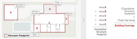
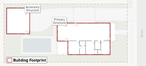
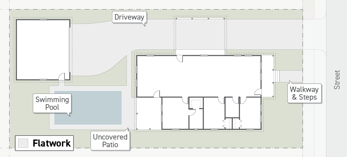
Structure footprints include all building footprints and structure footprints but do not include flatwork.


For covered structures, see Sec. 14.2.2.A.1. (Covered).
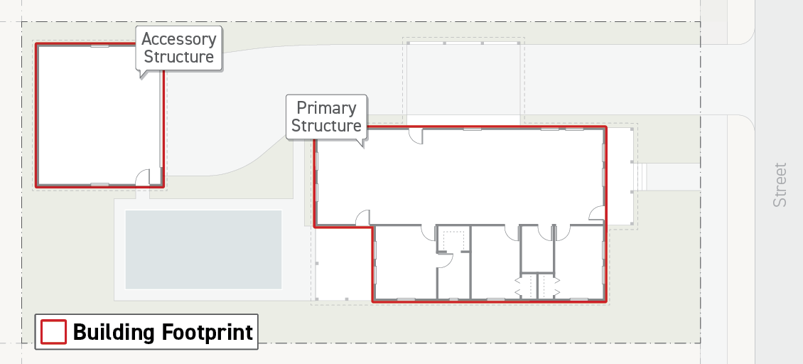
For structure footprint and building footprint determination, see Sec. 14.2.1. (Building Footprint).
Exceptions
Covered structures or portions of covered structures less than six feet in height, as measured from adjacent finished grade, are not included in the calculation of building coverage.
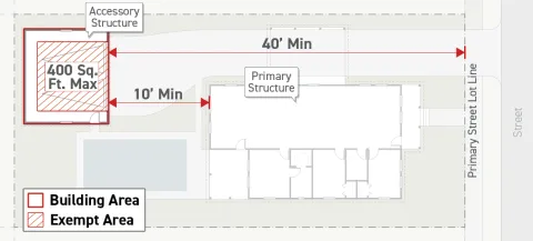
For lots with two or fewer dwelling units, having a House Form District (Div. 2B.3.) applied, a maximum of 400 square feet per lot is exempt from the calculation of building coverage, provided the building or structure is:
Detached from the primary building or structure by a minimum of 10 feet; and
Located a minimum of 40 feet from a primary street lot line.
Relief
Up to a 20 percent increase to the total allowed area of covered structures on a lot may be granted in accordance with Sec. 13B.5.2. (Adjustment).
Increased building coverage may be granted as a variance in accordance with Sec. 13B.5.3. (Variance).



Sec. 2C.2.2. Building Setbacks
Building setback is defined as the area on a lot not intended for buildings and structures. Building setbacks include primary street setbacks, side street setbacks, side setbacks, rear setbacks, alley setbacks, and special lot line setbacks.
Intent
The intent of the standards of this Section (Building Setbacks) is to provide open areas on the lot and help reduce the impact of buildings or structures on abutting sidewalks and neighboring development.
Applicability
Building setback standards apply to new construction or a major remodel. When the building setback standards apply, the standards apply to all buildings and structures on a lot.
Standards
All buildings and structures on the lot shall be located on or behind a minimum building setback, except where allowed in Subsection E. (Exceptions) below.
Measurement
All building setbacks are measured perpendicular to the applicable lot line:

A primary street setback is measured from the primary street lot line.
A side street setback is measured from the side street lot line.
A side setback is measured from the side lot line.
A rear setback is measured from the rear lot line.
An alley setback is measured from the alley lot line.
A special setback is measured from the special lot line.
Where a special setback is specified by the applied Form District (Part 2B.) as "Special: All", the setback is measured from all special lot lines.
Where a special setback is specified by the applied Form District (Part 2B.) as "Special: River" or "Special: Alley", the setback is measured from the special lot line as designated according to Sec. 14.2.12.C.3. (Special Lot Line).
Where a special setback is specified by the applied Form District (Part 2B.) as "Special: Other", the setback is measured from all special lot lines that are not otherwise specified.
Where an interior setback is specified, the setback is applied only to a lot within a unified development and shall be measured from any abutting lot within the same unified development. Where a lot within a unified development shares a lot line with a property outside of the unified development, the standard setback requirement applies.
For measurement on portions of a lot required for dedication of land, see Sec. 14.2.11. (Lot).
For measurement on a lot affected by a public access easement, see Sec. 14.2.17.B.1. (Building Setback).
Exceptions
The following are allowed to encroach beyond the building setback up to the minimum distance from the lot line specified below:
Horizontal Encroachments Allowed into Setbacks
Lot Lines
Primary/Side Street, Special
Side/Rear
Alley
Architectural Details (Sec. 14.2.5.A.1.a.)
Encroachment (max)
2'
2'
2'
Distance from lot line (min)
0'
2.5'
0'
Roof Projections (Sec. 14.2.5.A.1.b.)
Encroachment (max)
2.5'
2.5'
2.5'
Distance from lot line (min)
0'
2.5'
0'
Unenclosed Structures: Ground story
(Sec. 14.2.5.A.1.c.)Encroachment (max)
7'
5'
7'
Distance from lot line (min)
0'
2.5'
2.5'
Unenclosed Structures: Above ground story
(Sec. 14.2.5.A.1.d.)Encroachment (max)
5'
3'
3'
Distance from lot line (min)
0'
5'
2.5'
Enclosed Structures: Projecting
(Sec. 14.2.5.A.1.e.)Encroachment (max)
2.5'
1.5'
2.5'
Distance from lot line (min)
0'
2.5'
2.5'
Mechanical/Electrical Equipment:
Ground mounted (Sec. 14.2.5.A.1.f.)Encroachment (max)
1.5'
2.5'
2.5'
Distance from lot line (min)
15'
2.5'
0'
Mechanical/Electrical Equipment:
Wall mounted (Sec. 14.2.5.A.1.g.)Encroachment (max)
1.5'
1.5'
1.5'
Distance from lot line (min)
15'
2.5'
0'
Waste Enclosures (Sec. 14.2.5.A.1.h.)
Encroachment (max)
0'
unlimited
unlimited
Distance from lot line (min)
15'
2.5'
0'
Utility Equipment, Underground Structures, Flatwork, Fences and Walls, Vegetation, Outdoor Furniture
(Sec. 14.2.5.A.1.i. - Sec. 14.2.5.A.1.n.)Encroachment (max)
unlimited
unlimited
unlimited
Distance from lot line (min)
0'
0'
0'
For existing nonconforming building exceptions, see Sec. 12.2.1. (Coverage Exceptions).
Modifications to existing structures may encroach beyond the limitations specified in the Horizontal Encroachments Allowed Into Setbacks table, pursuant to Paragraph 1. above, only where such limitations conflict with California State Accessibility Standards or Fire Code. When greater encroachments are necessary, the horizontal encroachment shall extend the minimum amount necessary to achieve compliance.
Motor vehicle use areas and charging equipment that facilitates the charging of electric vehicles in electric vehicle parking stalls and any required use standards of the applied Use District (Part 5B.) for electric vehicle charging facilities and carports integrated with electric vehicle charging facilities are allowed to encroach into the required building setback but in no case shall encroach into the required Frontage and transition screen.
Relief
A deviation from a required setback along a special lot line that abuts a public right-of-way or public open space may be granted in accordance with Sec. 13B.5.1. (Alternative Compliance). In addition to the finding otherwise required by Sec. 13B.5.1. (Alternative Compliance), the Director shall also consider:
That the granting of the application will improve a site's connection with the public right-of-way or public open space.
Where a deviation from a required setback from a special river lot line is granted, the application will improve a site’s connection with the river or will improve river access.
A reduction in required setback of 20 percent or less may be granted in accordance with Sec. 13B.5.2. (Adjustment), provided the resulting setback is at least three feet.
A setback reduction may be granted as a variance in accordance with Sec. 13B.5.3. (Variance).

Div. 2C.3. Amenity
Sec. 2C.3.1. Lot Amenity Space
Lot amenity space is defined as an area on a lot designated to be used for active or passive recreation, including common outdoor amenity space, pedestrian amenity space, and public amenity space.
Intent
The intent of the standards of this Section (Lot Amenity Space) is to provide adequate recreation and open space areas for all tenants of a project, regardless of the use of a building, and to ensure such spaces are accessible, usable, and safe.
Applicability
Lot amenity space standards apply to new construction that results in an increase of 20 percent or more floor area, or to any lot modifications.
Standards
The cumulative area of lot amenity space provided on a lot shall not be less than that specified by the applied Form District (Part 2B.).
Each area provided to meet a lot amenity space requirement shall comply with the standards for one or more of the following eligible amenity space types.
Eligible Amenity Space Types
Amenity Space Type
Eligible
Common Outdoor Amenity Space (Sec. 2C.3.3.C.1.)
Yes
Pedestrian Amenity Space (Sec. 2C.3.3.C.2.)
Yes
Public Amenity Space (Sec. 2C.3.3.C.3.)
Yes
Private Outdoor Amenity Space (Sec. 2C.3.3.C.4.)
No
Common Indoor Amenity Space (Sec. 2C.3.3.C.5.)
No
A maximum of 25 percent of the total required lot amenity space may be privately accessible to individual tenant spaces, provided it meets the design standards in Sec. 2C.3.3.C.2. (Pedestrian Amenity Space).
Lot amenity space which is privately accessible pursuant to Paragraph 3. above shall abut and provide direct access to the assigned tenant space.
All required lot amenity space that is not private shall be made available to all tenants of the building, at no cost, from sunrise to sunset daily or during the hours of operation of the building, whichever results in a longer period of time.
Lot amenity space provided in accordance with Sec. 2C.3.3.C.3. (Public Amenity Space) may be eligible for credit toward the fee and dedication requirements in Div. 10.4. (Park Fees & Dedications), according to Sec. 10.4.8.B. (Privately Owned Park & Recreational Facilities).
Lot amenity space located above the ground story may be required to set back from the roof edge, see Chapter V. (Public Safety and Protection), Sec. 57.317. (Rooftop Gardens and Landscaped Roofs) of this Code.
Mechanical equipment and utility equipment shall not be located within a lot amenity space, or between a lot amenity space and the adjacent building facade.
All mechanical exhaust outlets shall be located a minimum horizontal distance of 10 feet and a minimum vertical distance of 15 feet from a lot amenity space.
At least 20 percent of any outdoor lot amenity space shall be shaded by using shade trees or shade structures. Any area that is covered by a shade structure or a shade tree canopy spread at maturity shall be considered as being shaded.
Lot amenity may be provided across a lot line when it is provided or required as part of a unified development, but shall be subject to all relevant standards in Sec. 2C.3.3. (Amenity Space Types) and Sec. 2C.3.4. (Amenity Design Standards).
Measurement
Lot amenity space is a percentage calculated by dividing the cumulative area of all lot amenity spaces by the lot area.
The minimum required lot amenity space is calculated by multiplying the minimum lot amenity percentage specified by the applied Form District (Part 2B.) by the lot area.
As a bonus for providing public space, outdoor amenity space area meeting Sec. 2C.3.3.C.3. (Public Amenity Space) counts as 1.25 square feet of lot amenity space for every one square foot of provided outdoor amenity space area.
Shade is calculated as the shadow cast on the publicly accessible open space measured at noon (12:00 p.m.) on the summer solstice.
For calculation of lot amenity space on a lot affected by a public access easement, see Sec. 14.2.17.B.2. (Lot Amenity Space).
In a unified development, the lot amenity requirement can be fulfilled for every individual lot by the above measurement, or the total area of all lots may be taken as the lot area to be multiplied by the lot amenity percentage requirement. Private outdoor amenity space cannot be used to fulfill the lot amenity requirement when the cumulative lot area is used for the calculation.
Exceptions
Where the calculation of lot amenity space requires less than 400 square feet, no lot amenity space is required.
When a lot modification involves an air space lot subdivision, the air space lot area is not used in the calculation for required lot amenity space.
Where the applied Form District (Part 2B.) identifies an eligible lot amenity alternative, in lieu of the otherwise required lot amenity space in this Section (Lot Amenity Space), a project may provide a lot amenity space meeting the requirements established for that listed lot amenity alternative type, as provided in Sec. 2C.3.5. (Lot Amenity Alternatives).
Where the applied Form District (Part 2B.) identifies an eligible lot amenity alternative, in lieu of the otherwise required lot amenity space in this Section (Lot Amenity Space), a project may provide a lot amenity space meeting the requirements established for that listed lot amenity alternative type, as provided in Sec. 2C.3.5. (Lot Amenity Alternatives).
Relief
Up to a 10 percent reduction to the total required area of lot amenity space may be granted in accordance with Sec. 13B.5.2. (Adjustment).
A reduction in required lot amenity space may be granted as a variance in accordance with Sec. 13B.5.3. (Variance).
Sec. 2C.3.2. Residential Amenity Space
Residential amenity space is defined as an area which is designed and intended to be used by occupants of dwelling units for recreational, domestic, or vocational purposes.
Intent
The intent of the standards of this Section (Residential Amenity Space) is to ensure projects that include housing provide residential tenants of a project with adequate access to open space, recreation, and shared amenities where the lot amenity space is insufficient, and to ensure such spaces are accessible, usable, and safe.
Applicability
Residential amenity space standards apply to any project that includes five or more dwelling units on a lot and involves any of the following project activities: new construction, a major remodel, a lot modification, or a use modification.
Standards
The cumulative area of residential amenity space provided on a lot shall not be less than that specified by the applied Form District (Part 2B.).
Each area provided to meet a residential amenity space requirement shall comply with the standards for one or more of the following eligible amenity space types.
Eligible Amenity Space Types
Amenity Space Type
Eligible
Common Outdoor Amenity Space (Sec. 2C.3.3.C.1.)
Yes
Pedestrian Amenity Space (Sec. 2C.3.3.C.2.)
Yes
Public Amenity Space (Sec. 2C.3.3.C.3.)
Yes
Private Outdoor Amenity Space (Sec. 2C.3.3.C.4.)
Yes
Common Indoor Amenity Space (Sec. 2C.3.3.C.5.)
Yes
At least 75 percent of the required residential amenity space shall be outdoors and meet the design standards of either Sec. 2C.3.3.C.1. (Common Outdoor Amenity Space) or Sec. 2C.3.3.C.4. (Private Outdoor Amenity Space).
A maximum of 65 square feet of required residential amenity space per dwelling unit may be private, provided that not more than 50 percent of the total required residential amenity space is private, and the private residential amenity space meets the design standards in Sec. 2C.3.3.C.4. (Private Outdoor Amenity Space).
Private residential amenity space shall abut and provide direct access to the assigned tenant space.
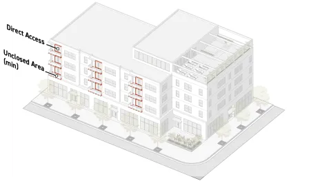
All required residential amenity space that is not private shall be made available to all tenants of the building, at no cost, from sunrise to sunset daily or during the hours of operation of the building, whichever results in a longer period of time.
Residential amenity space provided in accordance with Sec. 2C.3.3.C.3. (Public Amenity Space) may be eligible for credit towards the fee and dedication requirements outlined in Div. 10.4. (Park Fees & Dedications), according to Sec. 10.4.8.B. (Privately Owned Park & Recreational Facilities).
Residential amenity space located above the ground story may be required to set back from the roof edge, see Chapter V. (Public Safety and Protection), Sec. 57.317. (Rooftop Gardens and Landscaped Roofs) of this Code.
Mechanical equipment and utility equipment shall not be located within a residential amenity space, or between a residential amenity space and the adjacent building facade.
All mechanical exhaust outlets shall be located a minimum horizontal distance of 10 feet and a minimum vertical distance of 15 feet from a residential amenity space.
At least 20 percent of any outdoor residential amenity space shall be shaded by shade trees or shade structures.
Measurement
Residential amenity space is a percentage calculated by dividing the cumulative area of all residential amenity spaces by the total floor area allocated to dwelling units.
The minimum required residential amenity space is calculated by multiplying the total floor area allocated to dwelling units by the minimum percentage specified by the applied Form District (Part 2B.).
All lot amenity space provided may be credited toward the residential amenity space requirement.
As a bonus for providing public space, residential amenity space meeting Sec. 2C.3.3.C.3. (Public Amenity Space) counts at a rate of 1.25 square feet for every one square foot of public amenity space provided.
Any area that is covered by a shade structure or a shade tree canopy (as measured by spread at maturity) shall be considered as being shaded.
Relief
Up to a 10 percent reduction to the total required area of residential amenity space may be granted in accordance with Sec. 13B.5.2. (Adjustment).
A reduction in required residential amenity space may be granted as a variance in accordance with Sec. 13B.5.3. (Variance).

Sec. 2C.3.3. Amenity Space Types
Intent
The intent of the standards of this Section (Amenity Space Types) is to ensure that amenity spaces provided by projects are sufficient enough to provide spaces which are accessible, usable, and safe, and provide adequate access to open space, recreation, and shared amenities.
Applicability
Amenity space types are established in Sec. 2C.3.1. (Lot Amenity Space) and Sec. 2C.3.2. (Residential Amenity Space).
Standards
The following standards apply by type of amenity space.
Common Outdoor Amenity Space
Common outdoor amenity space is defined as a type of amenity space that is outdoors, open to all tenants of a building, and meets the following standards:
Common Outdoor Amenity Space
Amenity Space Standards
Specification
Reference
Outdoor Space
Required
Amenity Area (min)
400 sf
Horizontal Dimension (min)
15'
Adjacent Building Transparency (min)
15%
Planting Area
At Grade Plane Elevation (min)
25%
Above Grade Plane Elevation (min)
15%
Seating (min)
2 per 400 sf
Ground Floor Elevation
Not Required
Public Sidewalk/Way Adjacent
Not Required
Pedestrian-Oriented Lighting
Not Required
Publicly Accessible
Not Required
Amenity Features (min)
3
Pedestrian Amenity Space
Pedestrian amenity space is defined as a type of amenity space that is outdoors, located at ground-level, and is accessible to pedestrians and all tenants of a building by meeting the standards in the following table. See Div. 3C.1. (Build-To) for additional provisions related to pedestrian amenity spaces.
Pedestrian Amenity Space
Amenity Space Standards
Specification
Reference
Outdoor Space
Required
Amenity Area (min)
200 sf
Horizontal Dimension (min)
Enclosed (min)
15'
Unenclosed (min)
6'
Adjacent Building Transparency (min)
15%
Planting Area
At Grade Plane Elevation (min)
25%
Above Grade Plane Elevation (min)
n/a
Seating (min)
2 per 400 sf
Ground Floor Elevation
Required
Public Sidewalk/Way Adjacent
Required
Pedestrian-Oriented Lighting
Required
Publicly Accessible
Not Required
Amenity Features (min)
3
Public Amenity Space
Public amenity space is defined as a type of amenity space that is outdoors and, although privately owned, is open to the public, and meets the following standards:
Public Amenity Space
Amenity Space Standards
Specification
Reference
Outdoor Space
Required
Amenity Area (min)
400 sf
Horizontal Dimension (min)
15'
Adjacent Building Transparency (min)
15%
Planting Area
At Grade Plane Elevation (min)
25%
Above Grade Plane Elevation (min)
n/a
Seating (min)
2 per 400 sf
Ground Floor Elevation
Required
Public Sidewalk/Way Adjacent
Required
Pedestrian-Oriented Lighting
Required
Publicly Accessible
Required
Amenity Features (min)
3
Private Outdoor Amenity Space
Private outdoor amenity space a type of amenity space that is uncovered or unenclosed and is available to an assigned unit or tenant space, and meets the following standards:
Private Outdoor Amenity Space
Amenity Space Standards
Specification
Reference
Outdoor Space
Required
Amenity Area (min)
50 sf
Horizontal Dimension (min)
Enclosed (min)
8'
Unenclosed (min)
5'
Adjacent Building Transparency (min)
15%
Planting Area
n/a
Seating (min)
2 per 400 sf
Ground Floor Elevation
Not Required
Public Sidewalk/Way Adjacent
Not Required
Pedestrian-Oriented Lighting
Not Required
Publicly Accessible
Not Required
Amenity Features (min)
Not Required
Common Indoor Amenity Space
Common indoor amenity space is defined as a type of amenity space that is covered or enclosed, is legally required to be open to all tenants of a building, is intended to create opportunities for social and recreational activity for tenants, and meets the following standards:
Common Indoor Amenity Space
Amenity Space Standards
Specification
Reference
Outdoor Space
Not Required
Amenity Area (min)
400 sf
Horizontal Dimension (min)
10'
Adjacent Building Transparency (min)
n/a
Planting Area
n/a
Seating (min)
n/a
Ground Floor Elevation
Not Required
Public Sidewalk/Way Adjacent
Not Required
Pedestrian-Oriented Lighting
Not Required
Publicly Accessible
Not Required
Amenity Features (min)
1
Measurement
The enclosure of the horizontal dimension of an amenity space type shall be measured pursuant to Sec. 14.2.4. (Enclosure).
The grade plane elevation shall be determined per the standards written in Sec. 14.2.9. (Grade Plane Elevation).
For an amenity space type to be considered located at grade plane elevation, its elevation shall not be located at any elevation higher than the grade plane elevation calculation, but may be located lower.
For an amenity space type to be considered above grade plane elevation, it shall be located on a story that is above the first story of a structure.
Relief
A deviation from amenity space standards may be granted in accordance with Sec. 13B.5.1. (Alternative Compliance).
A deviation from any amenity space dimensional standard of 20 percent or less may be granted in accordance with Sec. 13B.5.2. (Adjustment).
A deviation from any amenity space standard may be granted as a variance in accordance with Sec. 13B.5.3. (Variance).
Sec. 2C.3.4. Amenity Design Standards
Intent
The intent of the standards of this Section (Amenity Design Standards) is to ensure that amenity spaces provide sufficient recreational area in a manner that is visually interesting, connects the development to its users or the public right-of-way, promotes environmental sensitivity, and creates opportunities for the congregation of individuals at the ground story or upper-stories of a development.
Applicability
Amenity space design standards are determined by the amenity space types in Sec. 2C.3.1. (Lot Amenity Space) and Sec. 2C.3.2. (Residential Amenity Space), and as established by Sec. 2C.3.3. (Amenity Space Types).
Standards
Outdoor Space
Where the amenity space is enclosed, it shall not be covered. Where the amenity space is covered, it shall not be enclosed.
No portion of an outdoor space may have a clear height of less than seven feet.
Portions of an outdoor space that are covered shall have a minimum clear height of 1.5 times the depth of the covered area.
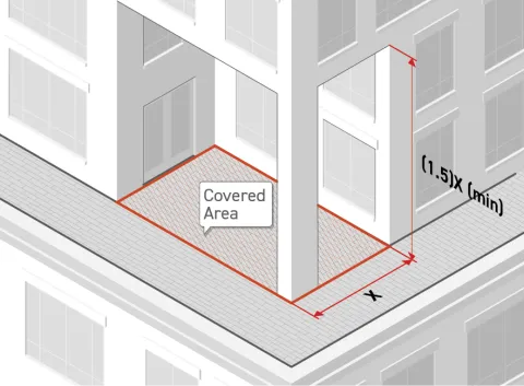
The following structures are exempt from the outdoor space standards above, provided all exempted structures have a cumulative area no greater than 20 percent of the contiguous amenity space area.
Unenclosed structures having a clear height of at least seven feet; and
An enclosed and covered structure, providing goods or services to tenants of the project or the public, having an area of no more than 25 square feet.

Amenity Area
Each amenity space shall provide an area of no less than the minimum amenity area required by the amenity space type.
Horizontal Dimension
Each amenity space shall have the minimum horizontal dimension set by the amenity space type.
Adjacent Building Transparency
Building facades adjacent to the amenity space shall provide at least the minimum transparency percentage required by the amenity space type for each story.
![[Error: Alt text was not generated.]](/sites/default/files/styles/large/public/zcode_images/2026.3.0/2C.3.4.5.png.webp?itok=6NSXE53H)
Planting Area
When an amenity space type satisfies its minimum planting area requirement at the grade plane elevation, the amenity space shall meet all other standards of the amenity space type within the minimum and maximum ground floor elevation as specified by the applied Frontage District (Part 3B.). For other applicable standards, see Sec. 4C.6.4.C.2. (Planting Areas).
An amenity space shall provide at least the required minimum percentage of the total area of the amenity space as planting area.
Seating
Permanent or movable seats shall be provided at the specified ratio based on the area in square feet of amenity space.
Each permanent or movable seat provided within the amenity space shall count as one.
Two linear feet of bench or seat wall provided within the amenity space shall be counted as one seat.
Ground Floor Elevation
The finished floor or ground surface of the amenity space shall be located within the minimum and maximum ground floor elevations specified by the applied Frontage District (Part 3B.).
For measurement of ground floor elevation, see Sec. 3C.6.2. (Ground Floor Elevation).
Public Sidewalk/Way Adjacent
The amenity space shall abut a public sidewalk or public way for a minimum width of 15 feet.
A pedestrian accessway having a minimum width of four feet shall connect the amenity space to the abutting public sidewalk or public way. No fixed wall or fence shall separate the amenity space from the abutting public sidewalk or public way for the minimum pedestrian accessway width.
The space shall not be separated from the public sidewalk or public way by any structure or landscaping, with the exception of a Type A1 or Type A2 frontage yard fence & wall type as specified in Sec. 3C.3.2. (Frontage Yard Fence & Wall).
Pedestrian-Oriented Lighting
The amenity space shall comply with the requirements of Sec. 4C.10.1.C.3. (Pedestrian-Oriented Lighting).
Publicly Accessible
The amenity space shall be made permanently available to the general public, at no cost, at minimum between sunrise and sunset daily.
Signs shall be posted at every public entrance to the amenity space in accordance with the Public Amenity Space Sign Standards as established by the Director, and in accordance with Div. 4C.11. (Signs). Standards include, but are not limited to, the following:
Minimum sign dimension, no less than 16 inches by 20 inches;
Sign location requirements;
Required posting of the hours of operation; and
Mandatory language regarding public access.
Amenity Features
The amenity space shall provide at least the minimum number of amenity features required by the amenity space type by providing from the list of options in the Amenity Features Menu as established by the Director, and shall be made permanently available to the tenants of the building.
The location and number of amenity features shall be identified on the proposed plans submitted to the Department of Building and Safety, with the accompanying dimensions called out as required by the selected options.
Measurement
Minimum amenity area is measured as an area in square feet calculated for each contiguous amenity space located on a lot. The area of the abutting parkway is not included in the total minimum amenity area.
The horizontal dimension shall be measured as the shortest horizontal distance along the boundaries of the amenity space, perpendicular to any boundary of the amenity space.
For measurement of transparency, see Div. 3C.4. (Transparency).
For measurement of ground floor elevation, see Sec. 3C.6.2. (Ground Floor Elevation).
The minimum width an amenity space is required to abut a public sidewalk or public way shall be measured following the geometry of the frontage lot line abutting the applicable public sidewalk or public way.
The minimum pedestrian accessway width shall be measured along the frontage lot line abutting the applicable public sidewalk or public way from one edge of the accessway perpendicularly to the opposite edge.
For measurement of pedestrian-oriented lighting, see Sec. 4C.10.1.D. (Measurement).
Relief
A deviation from any amenity design dimensional standard of 20 percent or less may be granted in accordance with Sec. 13B.5.2. (Adjustment).
A deviation from any amenity design standard may be granted as a variance in accordance with Sec. 13B.5.3. (Variance).


![[Error: Alt text was not generated.]](/sites/default/files/styles/larger/public/zcode_images/2026.3.0/2C.3.4.5.png?itok=TssJDCzS)
Sec. 2C.3.5. Lot Amenity Alternatives
Lot amenity alternatives are defined as space types with a predetermined set of design standards that may be used as an allowable alternative to the standard lot amenity space requirements of a Form District (Part 2B.).
Intent
The intent of the standards of this Section (Lot Amenity Alternatives) is to provide alternative options for the design of spaces for recreation and open space for the tenants of a project. Lot amenity alternatives establish design criteria for common and desirable open space typologies that both incentivize certain kinds of open spaces and potentially improve the feasibility of achieving required lot amenity space on constrained lots, while maintaining high-quality and contextually appropriate design.
Applicability
Lot amenity alternatives apply to projects with a lot amenity space requirement, as established in Sec. 2C.3.1. (Lot Amenity Space) on a lot with an applied Form District (Part 2B.) that lists one or more eligible lot amenity alternative types.
Lot amenity alternatives are optional alternatives to the lot amenity space requirements in Sec. 2C.3.1. (Lot Amenity Space), except projects utilizing the Corridor Transitions Incentive Program in Sec. 9.2.4. (Corridor Transitions Incentive Program) shall utilize a Lot Amenity Alternative Type.
Standards
General
Where the applied Form District (Part 2B.) lists one or more lot amenity alternative types, a project may provide a lot amenity space that meets the standards established in Paragraph 2. (Lot Amenity Alternative Types), below for any one of the lot amenity alternative types listed in the Form District (Part 2B.).
The provided lot amenity alternative shall be considered to meet the lot amenity space requirement for the lot, even if providing an eligible lot amenity alternative type results in providing less total lot amenity space on the lot than would otherwise be required pursuant to Sec. 2C.3.1. (Lot Amenity Space).
Projects providing a lot amenity alternative are still subject to any required Residential Amenity Space (Sec. 2C.3.2.).
Lot Amenity Alternative Types
Courtyard
Width
The width of the courtyard shall be a minimum of 30 percent of the lot width, or a minimum of 15 feet, whichever is greater, measured parallel to the applicable primary street lot line.
Depth
The depth of the courtyard shall be a minimum of 40 percent of the lot depth, measured perpendicular to the applicable primary street lot line.
Outdoor Space
The entirety of the courtyard space shall meet the requirements of Sec. 2C.3.4.C.1. (Outdoor Space).
Location
The courtyard shall be placed in one of the following locations on the lot:
Abutting the front yard on a lot, so as to create a courtyard that extends backward into the lot starting from the front yard or a courtyard that connects the front yard to another outdoor space meeting the standards of Sec. 4C.3.4.C.1. (Outdoor Space) on the lot.
An internal courtyard, surrounded on all sides by buildings or structures and contained entirely within a single lot.
Abutting an at-grade lot amenity space on an abutting lot, so as to create the effect of one large open space across multiple lots.
Paseo
Width
The width of the paseo shall be a minimum of 10 percent of the lot width, or a minimum of 10 feet, whichever is greater, measured parallel to the applicable primary street lot line.
Depth
The depth shall be a minimum of 60 percent of the lot depth, measured perpendicular to the applicableprimary street lot line.
Covered Area
The entirety of the paseo space shall meet the requirements of Sec. 2C.3.4.C.1. (Outdoor Space).
Pedestrian Pathway
An unobstructed pathway with direct access to the primary street lot line shall be provided with a minimum width of four feet along the entire depth of the paseo space.
Location
The paseo space shall be located between one or more buildings on the lot.
Rear Yard
Width
The width of the rear yard shall be a minimum of 50 percent of the lot width, measured parallel to the applicable primary street lot line.
Depth
The depth shall be a minimum of 10 percent of the lot depth, or a minimum of 15 feet, whichever is greater, measured perpendicular to the applicable primary street lot line.
Covered Area
The entirety of the rear yard space shall meet the requirements of Sec. 2C.3.4.C.1. (Outdoor Space), with the exception of portions of the rear yard space located within the required rear setback, which shall be open to the sky except for the encroachments allowed pursuant to Subsection E. (Exceptions) of Sec. 2C.2.2. (Building Setbacks).
Location
The rear yard shall be located abutting the rear lot line.
Measurement
General
A lot amenity alternative is measured as provided or not provided based on whether the design of a lot amenity space meets the standards of an eligible lot amenity alternative type specified by the applied Form District (Part 2B.).
Width
The width of a lot amenity alternative type shall be measured parallel to the primary street lot line and the minimum width shall be maintained along the entire required depth of the space.
Depth
The depth of a lot amenity alternative type shall be measured perpendicular to the primary street lot line and the minimum depth shall be maintained along the entire required width of the space.
Covered Area
For the measurement of an uncovered space, see Sec. 14.2.2. (Covered Area (%)).
Relief
No relief from the design standards established in Paragraph 2. (Lot Amenity Alternative Types) of Subsection C. (Standards), above, shall be permitted. Projects may instead defer to the standard lot amenity space requirements, pursuant to Sec. 2C.3.1. (Lot Amenity Space), including any relief allowed pursuant to that Section.
Div. 2C.4. Floor Area Ratio & Height
Sec. 2C.4.1. Floor Area Ratio (FAR)
Floor area ratio or FAR is defined as the measurement of the total floor area of all buildings on a lot in relation to the size of the lot.
Intent
The intent of the standards of this Section (Floor Area Ratio (FAR)) is to regulate the bulk and massing of buildings on a lot.
Applicability
Floor area ratio standards apply to new construction or a lot modification. When the floor area ratio standards apply, they apply to all buildings and structures located on a lot.
Standards
Floor Area Ratio (FAR)
A lot shall not exceed the maximum floor area ratio specified in the applied Form District (Part 2B.).
Base
When floor area ratio (FAR) is further specified by “Base”, in the applied Form District (Part 2B.), a lot shall not exceed the maximum Base floor area ratio without meeting the requirements of Div. 9.3. (Community Benefits Program), or an applicable Specific Plan, Supplemental District, or Special Zone.
Bonus
When floor area ratio (FAR) is further specified by “Bonus”, in the applied Form District (Part 2B.), a lot may exceed the maximum Base floor area ratio up to the maximum Bonus floor area ratio as allowed in Div. 9.3. (Community Benefits Program), or an applicable Specific Plan, Supplemental District, or Special Zone.
Tier 1 Bonus
When floor area ratio (FAR) is further specified by “Tier 1 Bonus”, in the applied Form District (Part 2B.), a lot may exceed the Base floor area ratio up to the maximum tier 1 bonus floor area ratio of the applied Form District (Part 2B.) as allowed in Div. 9.3. (Community Benefits Program), or an applicable Specific Plan, Supplemental District, or Special Zone.
Tier 2 Bonus
When floor area ratio (FAR) is further specified by “Tier 2 Bonus”, in the applied Form District (Part 2B.), a lot may exceed the Base floor area ratio and tier 1 bonus floor area ratio up to the maximum tier 2 bonus floor area ratio as allowed in Div. 9.3. (Community Benefits Program), or an applicable Specific Plan, Supplemental District, or Special Zone.
Measurement
FAR is calculated by dividing the total floor area on a lot by the lot area.
For the measurement of floor area, see Sec. 14.2.7. (Floor Area).
For the purpose of calculating FAR, portions of a lot designated for private streets may be counted as lot area. For the measurement of lot area, see Sec. 2C.1.1. (Lot Area).
For the purpose of calculating FAR, lot area is the same as buildable area referred to in the City of Los Angeles Charter, Article I. (Incorporation and Powers), Sec. 104. (e) (Floor Area Restriction).
The Downtown Community Plan Implementation Overlay may define and measure buildable area differently than outlined in Paragraph 4. above for the purpose of calculating the maximum floor area using bonus FAR.
Exceptions
For existing nonconforming building exceptions, see Sec. 12.2.2. (Floor Area Ratio & Height Exceptions).
Projects participating in incentive programs intended to implement State law, including the State Density Bonus Program (Sec. 9.2.1.), the Affordable Housing Incentive Program (Sec. 9.2.2.), the Opportunity Corridors Housing Incentive Program (Sec. 9.2.2.), the Corridor Transitions Incentive Program (Sec. 9.2.3.), Transit Oriented Incentive Program (Sec. 9.2.4.), the Permanent Supportive Housing Incentive Program (Sec. 9.4.1.), or the Accessory Dwelling Unit Incentive Program (Div. 9.5.), may exceed the maximum floor area ratio or any applicable bonus FAR of the applied Form District (Part 2B.).
Relief
For existing nonconforming building exceptions, see Sec. 12.2.2. (Floor Area Ratio & Height Exceptions).
For projects that include multiple parcels having different applied Form Districts (Part 2B.), floor area averaging across the development site may be granted, in accordance with Sec. 13B.2.2. (Class 2 Conditional Use Permit).
Supplemental Findings
In addition to the findings in Sec. 13B.2.2. (Class 2 Conditional Use Permit), the Zoning Administrator shall also find that the project meets the following conditions:
The project meets the definition of unified development,
All lots included in the project have a Commercial-Mixed Use District (Div. 5B.5.), Industrial-Mixed Use District (Div. 5B.6.), or Industrial Use District (Div. 5B.7.) applied, or the project is located entirely in the Downtown Community Plan Area and all lots included in the project have a Residential-Mixed Use District (Div. 5B.4.), Commercial-Mixed Use District (Div. 5B.5.), Industrial-Mixed Use District (Div. 5B.6.), or Industrial Use District (Div. 5B.7.) applied.
The total floor area of all structures on an individual lot may only exceed the FAR allowed pursuant to the applied Form District (Part 2B.) if the total floor area across all lots in the unified development does not exceed the sum of the maximum FAR calculated based on the maximum FAR specified by each applied Form District (Part 2B.).
Supplemental Procedures
If the Zoning Administrator approves floor area averaging, then prior to the issuance of any building permits the property owner shall file with the Department of Building and Safety a covenant running with the land that specifies the following:
The operation and maintenance of the development as a unified development is continued into perpetuity;
The floor area used and the remaining unbuilt floor area, if any, is allocated to each lot;
The unifying design elements are maintained and continued into perpetuity;
The covenant is binding on all assigns and successors in interest; and
An individual or entity is specified to be responsible and accountable for compliance and the fee for the annual inspection of compliance by the Department of Building and Safety, required pursuant to Sec. 15.3.12. (Annual Inspection of FAR Averaging & Density Transfer Covenants).
Sec. 2C.4.2. Height in Feet
Height in feet is defined as the vertical dimension of a building or structure measured in feet.
Intent
The intent of the standards of this Section (Height In Feet) is to provide adequate light, air, safety, and to protect the character of an area and the interests of the general public.
Applicability
Height in feet standards apply to all new construction or an exterior modification on a lot where the applied Form District (Part 2B.) specifies a maximum height in feet standard.
Standards
Buildings and structures shall not exceed the maximum height in feet specified in the applied Form District (Part 2B.).
Measurement
Maximum height in feet is measured as the vertical distance from grade plane to the top of the roof structure. One or more grade plane modules may be established for each building, as shown below. See Sec. 14.2.9.D. (Building Module Method).

Regardless of established grade plane, buildings shall also comply with ground floor elevation standards in Article 3. (Frontage).
Exceptions
The following are allowed beyond the maximum height in feet, as specified below:
Allowed Vertical Encroachments
Form District Height (max)
45' or less
> 45' to 90'
> 90'
Mechanical/Electrical Equipment: Roof Mounted
(Sec. 14.2.5.B.1.b.)Encroachment (max)
3'
5'
10'
Setback from roof edge (min)
3'
3'
5'
Architectural Elements (Sec. 14.2.5.B.1.c.)
Encroachment (max)
5'
5'
10'
Setback from roof edge (min)
3'
3'
5'
Vertical Circulation (Sec. 14.2.5.B.1.d.)
Encroachment (max)
10'
20'
20'
Setback from roof edge (min)
0'
0'
0'
Safety Barriers (Sec. 14.2.5.B.1.e.)
Encroachment (max)
6'
6'
6'
Setback from roof edge (min)
0'
0'
0'
Unenclosed Structures (Sec. 14.2.5.B.1.f.)
Encroachment (max)
8'
8'
8'
Setback from roof edge (min)
5'
5'
5'
Flatwork (Sec. 14.2.5.B.1.g.)
Encroachment (max)
2.5'
2.5'
2.5
Setback from roof edge (min)
1'
1'
1'
Vegetation (Sec. 14.2.5.B.1.h.)
Encroachment (max)
unlimited
unlimited
unlimited
Setback from roof edge (min)
1'
1'
1'
Modifications to existing structures may encroach beyond the limitations of the Allowed Vertical Encroachments table, pursuant to Paragraph 1. above, only where such limitations conflict with California State Accessibility Standards or Fire Code. When greater encroachments are necessary, the vertical encroachment shall extend the minimum amount necessary to achieve compliance.
Projects participating in incentive programs intended to implement State law, including the State Density Bonus Program (Sec. 9.2.1.), the Affordable Housing Incentive Program (Sec. 9.2.2.), the Opportunity Corridors Housing Incentive Program (Sec. 9.2.3.), the Corridor Transitions Incentive Program (Sec. 9.2.4.), Transit Oriented Incentive Program (Sec. 9.2.5.), the Permanent Supportive Housing Incentive Program (Sec. 9.4.1.), or the Accessory Dwelling Unit Incentive Program (Div. 9.5.), may exceed the maximum height in feet of the applied Form District (Part 2B.).
Relief
Increased building maximum height in feet of 20 percent or less may be granted in accordance with Sec. 13B.5.2. (Adjustment).
Increased vertical encroachments of 20 percent or less may be granted in accordance with Sec. 13B.5.2. (Adjustment).
Increased maximum building height in feet or vertical encroachments may be granted as a variance in accordance with Sec. 13B.5.3. (Variance).

Sec. 2C.4.3. Height in Stories
Height in stories is defined as the vertical dimension of a building measured in stories.
Intent
Maximum height in stories standards are intended to provide adequate light, air, safety, and to protect the character of an area and the interests of the general public. Intended to help provide variation in building heights, maximum height in stories standards help ensure that story heights are not reduced to fit within a maximum height in feet.
Minimum height in stories standards are intended to provide a method of establishing a minimum level of intensity on a lot, and ensure that lots are not underdeveloped.
Applicability
Maximum height in stories standards apply to new construction or an exterior modification on a lot where the applied Form District (Part 2B.) specifies a maximum height in stories standard.
Minimum height in stories standards apply to new construction or an exterior modification on a lot where the applied Form District (Part 2B.) specifies a minimum height in stories standard.
Standards
Maximum Height in Stories
Buildings and structures shall not exceed the "Height in stories (max)” specified in the applied Form District (Part 2B.).
When height in stories is further specified by “Maximum”, buildings and structures shall not exceed the Maximum height in stories. When “None” is indicated, there is no limitation to building and structure height except if a minimum story height is required.
Minimum Height in Stories
When height in stories is further specified by “Minimum”, portions of a building and structure shall be built to the minimum height in stories specified, as follows:
Only those portions of the building fulfilling the build-to width standard in the applicable Frontage District (Part 3B.) are required to be built to the minimum height in stories.
Each portion of building width used to meet the minimum build-to width standard specified by the applied Frontage District (Part 3B.) shall contain floor area for a depth no less than 15 feet on every story above the ground floor elevation up to the minimum height in stories specified by the applied Form District (Part 2B.)
When height in stories is further specified by “Minimum (Bonus)” the following standards apply:
The minimum height in stories applies only to projects utilizing bonus FAR.
The minimum height in stories requirement does not apply to predominantly non-residential projects. For the purposes of this rule, "predominantly non-residential" means a project with more than 50 percent of the total floor area allocated to non-residential uses (not including uses in the eating & drinking, personal services, and retail use groups).
Only those portions of the building fulfilling the build-to width standard in the applicable Frontage District (Part 3B.) are required to be built to the minimum height in stories.
Each portion of building width used to meet the minimum build-to width standard specified by the applied Frontage District (Part 3B.) shall contain floor area for a depth no less than 15 feet on every story above the ground floor elevation up to the minimum height in stories specified by the applied Form District (Part 2B.).
Base
When height in stories is further specified by “Base”, buildings and structures shall not exceed the Base maximum height in stories without meeting the requirements of Div. 9.3. (Community Benefits Program), or an applicable Specific Plan, Supplemental District, or Special Zone.
Bonus
When height in stories is further specified by “Bonus”, buildings and structures may exceed the Base maximum height in stories up to the bonus height of the applied Form District (Part 2B.) as allowed in Div. 9.3. (Community Benefits Program), or an applicable Specific Plan, Supplemental District, or Special Zone.
Tier 1 Bonus
When height in stories is further specified by “Tier 1 Bonus”, buildings and structures may exceed the Base maximum height in stories up to the tier 1 bonus height of the applied Form District (Part 2B.) as allowed in Div. 9.3. (Community Benefits Program), or an applicable Specific Plan, Supplemental District, or Special Zone.
Tier 2 Bonus
When height in stories is further specified by “Tier 2 Bonus”, buildings and structures may exceed the Base maximum height in stories and maximum tier 1 bonus height up to the maximum tier 2 bonus height of the applied Form District (Part 2B.) as allowed in Div. 9.3. (Community Benefits Program), or an applicable Specific Plan, Supplemental District, or Special Zone.
Measurement
Height in stories is measured as the number of stories above the ground floor elevation for each module of the building as shown below. See Sec. 14.2.9.D. (Building Module Method).
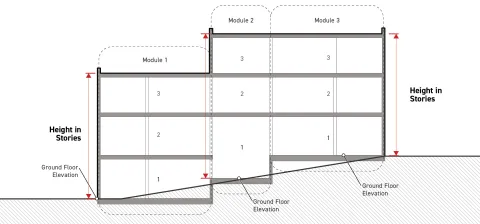

For determining ground story, see Sec. 14.2.10.A. (Ground Story).
Structures without Stories
For determining the maximum allowed height for structures that do not contain habitable stories when the applied form district does not also regulate height in feet, the maximum allowed height shall be determined by multiplying the maximum height in stories by 15 feet per allowable story. This resulting product shall be the maximum height allowed for a structure containing no habitable stories.
When the applied form district includes a bonus maximum height in stories, the number of bonus stories specified shall be used to determine the maximum allowable height of structures containing no habitable stories.
Exceptions
The following encroachments are allowed beyond the maximum height in stories, as specified below:
Allowed Vertical Encroachments
Form District Height (max)
3 Stories or Less
3 to 7 Stories
More than 7 Stories
Mechanical/Electrical Equipment: Roof Mounted
(Sec. 14.2.5.B.1.b.)Encroachment (max)
3'
5'
10'
Setback from roof edge (min)
3'
3'
5'
Architectural Elements (Sec. 14.2.5.B.1.c.)
Encroachment (max)
5'
5'
10'
Setback from roof edge (min)
3'
5'
5'
Vertical Circulation (Sec. 14.2.5.B.1.d.)
Encroachment (max)
10'
20'
20'
Setback from roof edge (min)
0'
0'
0'
Safety Barriers (Sec. 14.2.5.B.1.e.)
Encroachment (max)
6'
6'
6'
Setback from roof edge (min)
0'
0'
0'
Unenclosed Structures (Sec. 14.2.5.B.1.f.)
Encroachment (max)
8'
8'
8'
Setback from roof edge (min)
5'
5'
5'
Flatwork (Sec. 14.2.5.B.1.g.)
Encroachment (max)
2.5'
2.5'
2.5'
Setback from roof edge (min)
1'
1'
1'
Vegetation (Sec. 14.2.5.B.1.h.)
Encroachment (max)
unlimited
unlimited
unlimited
Setback from roof edge (min)
1'
1'
1'
Modifications to existing structures may encroach beyond the limitations of the Allowed Vertical Encroachments table, pursuant to Paragraph 1. above, only where such limitations conflict with California State Accessibility Standards or Fire Code. When greater encroachments are necessary, the vertical encroachment shall extend the minimum amount necessary to achieve compliance.
Projects participating in incentive programs intended to implement State law, including the State Density Bonus Program (Sec. 9.2.1.), the Opportunity Corridors Housing Incentive Program (Sec. 9.2.2.), the Corridor Transitions Incentive Program (Sec. 9.2.3.), Transit Oriented Incentive Program (Sec. 9.2.4.), the Permanent Supportive Housing Incentive Program (Sec. 9.4.1.), or the Accessory Dwelling Unit Incentive Program (Div. 9.5.), may exceed the maximum height in stories or any applicable bonus height of the applied Form District (Part 2B.).
Relief
An increase in maximum height in stories may be granted as a variance in accordance with Sec. 13B.5.3. (Variance).
A reduction in minimum height in stories of one story may be granted in accordance with Sec. 13B.5.2. (Adjustment).
A reduction in minimum height in stories may be granted as a Class 1 Conditional Use Permit. In addition to the findings otherwise required by Sec. 13B.2.1. (Class 1 Conditional Use Permit), the Zoning Administrator shall also find that the reduction would be consistent with prevailing heights along the block face.
A reduction in minimum height in stories may be granted as a variance in accordance with Sec. 13B.5.3. (Variance).


Sec. 2C.4.4. City Hall Height Restriction
City Hall height restriction is defined as a restriction to the vertical dimension of a building based-on proximity and height relative to Los Angeles City Hall.
Intent
The intent of the standards of this Section (City Hall Height Restriction) is to maintain the prominence of the historic Los Angeles City Hall tower in the Downtown Civic Center area by ensuring that the height of the tower remains significantly taller than any other building surrounding City Hall.
Applicability
City Hall height restriction standards apply to new construction or an exterior modification on a lot where the applied Form District (Part 2B.) specifies "Required" for City Hall height restriction.
Standards
For portions of buildings or structures within 675 feet of City Hall, no portion of a building or structure may be located above an elevation equal to 1.5 times its distance from City Hall plus the elevation at the base of City Hall, as measured from sea level.
For portions of buildings or structures located more than 675 feet from City Hall, no portion of a building or structure may be located above the elevation of the topmost point of City Hall.

Measurement
Maximum Height
The maximum elevation of a building or portion of a building shall be calculated using the following formula: 1.5(distance) + 295 feet = maximum elevation above sea level
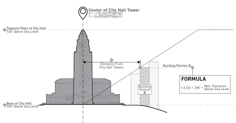
Distance from City Hall Tower
Distance from City Hall is measured horizontally outward from the center point of its tower. The center point of the tower is considered to be located at the following geographic coordinates:
X = -118.242757887301
Y = 34.0536897906413
Topmost point of City Hall Tower
The topmost point of the City Hall tower is considered to be located at 745 feet above sea level. Any portion of a building or structure located below this elevation is considered to be located below the topmost point of the tower.
Base of City Hall Tower
The base of City Hall is considered to be located at 295 feet above sea level.
Relief
An increase in building height above the City Hall height restriction may be granted as a variance in accordance with Sec. 13B.5.3. (Variance).

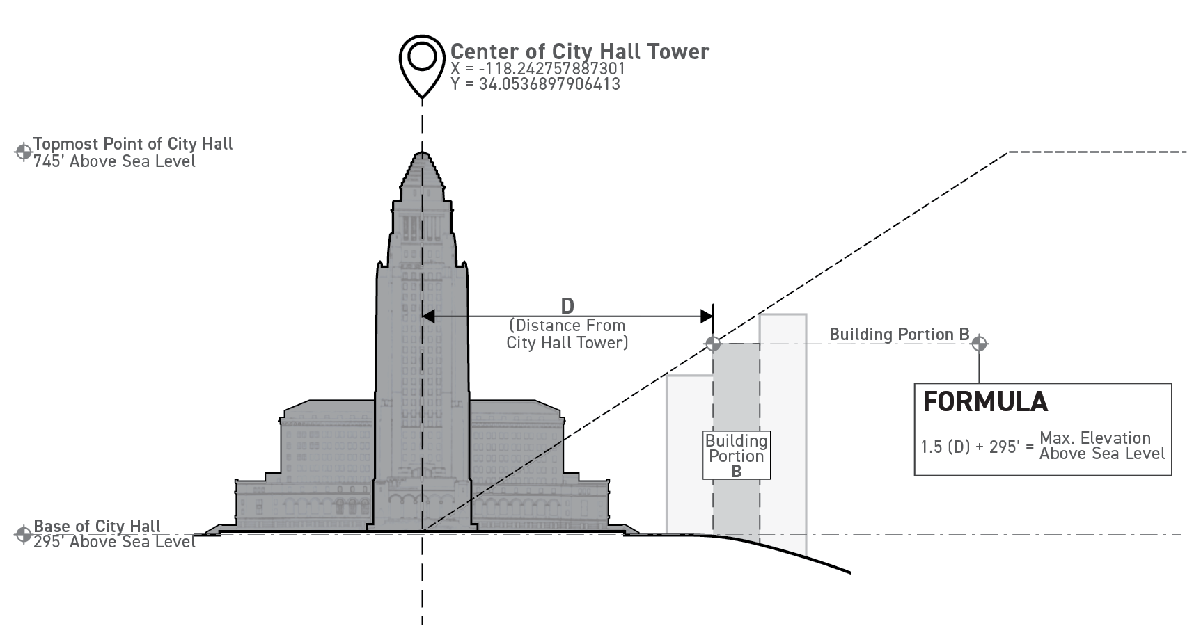
Div. 2C.5. Building Mass
Sec. 2C.5.1. Building Width
Building width is defined as the horizontal dimension of any building or collection of abutting buildings on a lot.
Intent
The intent of the standards of this Section (Building Width) is to promote fine-grained patterns of development and prevent long buildings that are significantly out of context with traditional patterns by breaking wide buildings into multiple, clearly distinguished building widths, and to encourage larger projects to provide open space for pedestrians and recreation.
Applicability
Building width standards apply to new construction or an exterior modification of any frontage lot line-facing buildings or structures. When the building width standards apply, the standards only apply to those portions of a building or structure located above the ground floor elevation.
Standards
General
No applicable building or collection of abutting buildings located on the same lot shall be wider than the maximum building width specified by the applied Form District (Part 2B.).
In order to establish buildings on the same lot as separate buildings for the purpose of measuring maximum building width, a building break shall be provided between the buildings.
Buildings that are located on separate lots, share no interior circulation, and are structurally independent, are considered separate buildings for the purpose of measuring building width.
A building on a corner lot within the build-to zone area of overlap is allowed to exceed the maximum building width by up to 40 feet along both primary street lot lines and side street lot lines.
All applicable buildings and collections of abutting buildings located on the same lot shall be separated by at least the minimum building break dimension for the full depth of the building in order to establish them as separate buildings for the purpose of measuring building width.
No building or structure shall encroach into the building break, except where allowed in Subsection E. (Exceptions) below.
Bonus Building Width
Notwithstanding Paragraph 1. (General), above, buildings and structures may exceed the maximum building width up to the bonus building width in feet of the applied Form District (Part 2B.) as allowed by Div. 9.3. (Community Benefits Program), if the participating project provides the required restricted affordable units or other public benefits.
Projects participating in incentive programs intended to implement State law, including the State Density Bonus Program (Sec. 9.2.1.), the Opportunity Corridors Housing Incentive Program (Sec. 9.2.2.), the Corridor Transitions Incentive Program (Sec. 9.2.3.), Transit Oriented Incentive Program (Sec. 9.2.4.), the Permanent Supportive Housing Incentive Program (Sec. 9.4.1.), or the Accessory Dwelling Unit Incentive Program (Div. 9.5.), may exceed the maximum bonus building width of the applied Form District (Part 2B.).
Measurement
Building width is measured horizontally and parallel to each primary street lot line and side street lot line from one end of an applicable building or collection of abutting buildings to the opposite end.

For lot line-facing, see Sec. 14.2.6. (Facing).
For measuring building width on irregular lot lines, see Sec. 14.2.14. (Irregular Lot lines).
A building break is measured perpendicular to the outermost surface of each applicable portion of a building both vertically and horizontally.
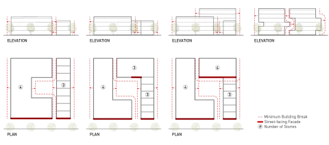
Exceptions
Encroachments
The following are allowed to encroach into the building break, as listed below:
Allowed Horizontal Encroachments
Architectural Details (Sec. 14.2.5.A.1.a.)
Encroachment (max)
2’
Clear width (min)
3’
Roof Projections (Sec. 14.2.5.A.1.b.)
Encroachment (max)
2.5’
Clear width (min)
3’
Unenclosed Structures: Above Ground Story
(Sec. 14.2.5.A.1.d. - Sec. 14.2.5.A.1.d.)Encroachment (max)
5’
Clear width (min)
3’
Mechanical/Electrical Equipment (Sec. 14.2.5.A.1.f. - Sec. 14.2.5.A.1.g.)
Encroachment (max)
1.5’
Clear width (min)
3’
Building Break Amenity Space Alternative
As an alternative to a building break, a street-facing amenity space that meets the following standards may be used to establish buildings or collections of abutting buildings as separate buildings for the purpose of measuring maximum building width:
The amenity space shall meet the design standards of an amenity space type pursuant to Sec. 2C.3.3. (Amenity Space Types) and for outdoor space pursuant to Sec. 2C.3.4.C.1. (Outdoor Space).
The amenity space width shall be at least two times the minimum building break dimension specified in the applied Form District (Part 2B.), measured parallel to the applicable street lot line.
The amenity space width shall not be greater than the maximum building width, measured parallel to the applicable street lot line.
The amenity space depth shall be at least five times the minimum building break dimension specified in the applied Form District (Part 2B.), measured perpendicular to the street lot line.
A minimum of 75 percent of the amenity space area shall meet the design standards in Sec. 2C.3.3.C.2. (Pedestrian Amenity Space).
The amenity space may count toward the required minimum build-to width required by the applied Frontage District (Part 3B.), provided it meets the requirements of Sec. 3C.1.3.E. (Exceptions).
Any portion of the amenity space may count toward lot amenity space and residential amenity space, provided it meets all applicable standards.
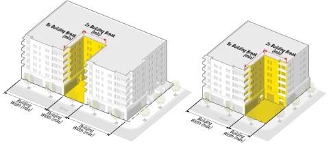
Relief
Increased building width of 20 percent or less or reduced building break of 20 percent or less may be granted in accordance with Sec. 13B.5.2. (Adjustment).
Increased building width or reduced building break may be granted as a variance in accordance with Sec. 13B.5.3. (Variance).

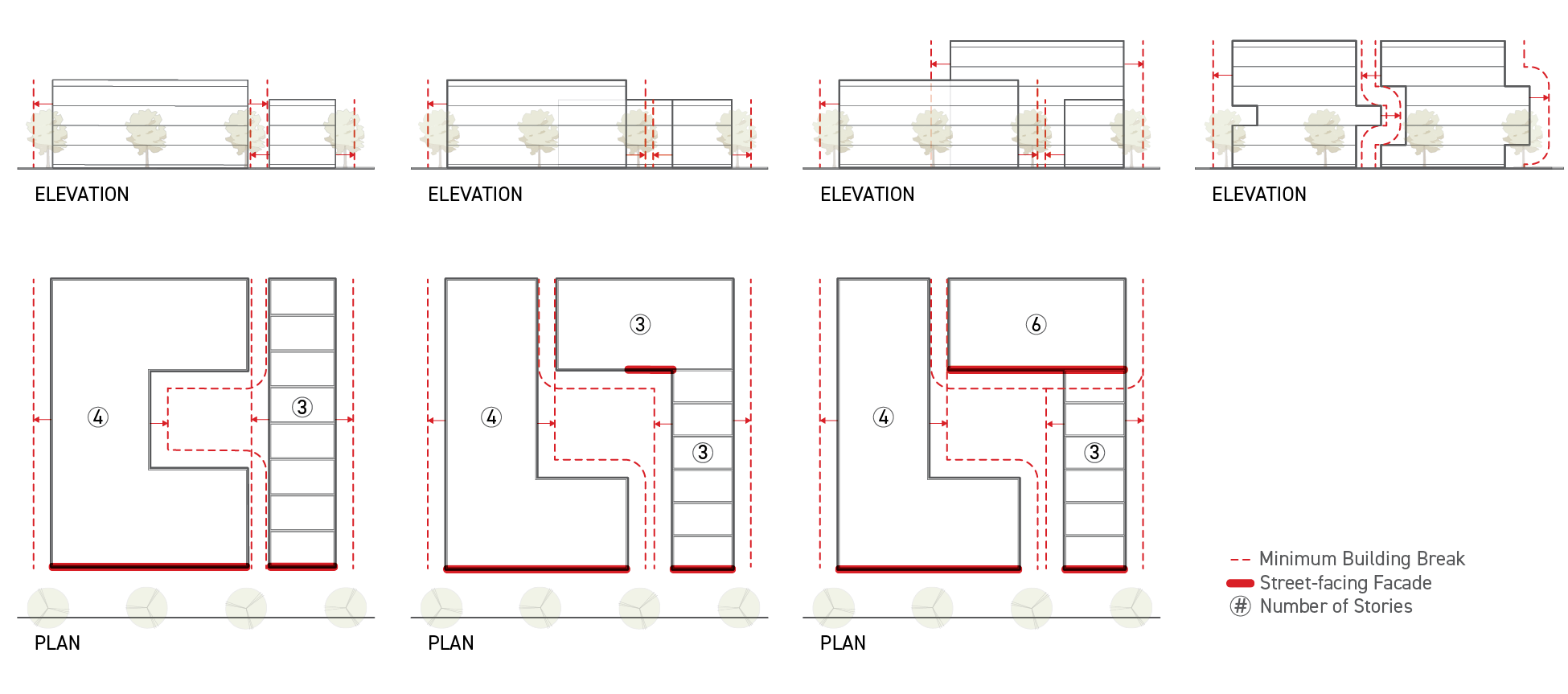

Div. 2C.6. Upper-Story Bulk
Sec. 2C.6.1. Street Step-Back
Street step-back is a step-like recess in the massing of a building that requires upper stories to be pushed back from the lower stories from the street.
Intent
The intent of the standards of this Section (Street Step-Back) is to reduce the perceived bulk and mass of a building along facades facing public ways, ensuring a height along the street that is appropriate to its neighboring context, while allowing for additional building height.
Applicability
Street step-back standards apply to new construction, a major remodel, or a facade modification of buildings or structures on a lot that face a frontage lot line.
Standards
The following standards shall be met for a minimum of 85 percent of the building width:
When the applied Form District (Part 2B.) specifies a maximum number of stories without a step-back, all stories above that maximum shall be stepped back from the street-facing facade by at least the minimum street step-back depth, as specified by the applied Form District (Part 2B.).
No building or structure shall extend into a minimum street step-back depth, except where allowed in Subsection E. (Exceptions) below.
Buildings having a height less than the maximum stories without street step-back are not required to provide a street step-back.

Measurement
Stories Without Street Step-back
When the applied Form District (Part 2B.) specifies a maximum number of stories without a step-back, that maximum is measured according to Sec. 2C.4.3. (Height in Stories).
Street Step-back Depth
Minimum street step-back depth is measured as the horizontal distance from the outermost edge of the building facade with the topmost story without street step-back to the outermost edge of the facade of the stepped back stories. Street step-back depth is required regardless of the provided or required building setback.

Exceptions
The following are allowed to encroach beyond the street step-back as listed below:
Allowed Horizontal Encroachments
Architectural Details (Sec. 14.2.5.A.1.a.)
Encroachment (max)
2’
Roof Projections (Sec. 14.2.5.A.1.b.)
Encroachment (max)
2.5’
Unenclosed Structures (Sec. 14.2.5.A.1.c. - Sec. 14.2.5.A.1.d.)
Encroachment (max)
5’
Enclosed Structures: Projecting (Sec. 14.2.5.A.1.e.)
Encroachment (max)
2.5’
Mechanical/Electrical Equipment (Sec. 14.2.5.A.1.f. - Sec. 14.2.5.A.1.g.)
Encroachment (max)
1.5’
Allowed Vertical Encroachments
Mechanical/Electrical Equipment: Roof Mounted (Sec. 14.2.5.B.1.b.)
Encroachment (max)
5'
Setback from roof edge (min)
3'
Architectural Elements (Sec. 14.2.5.B.1.c.)
Encroachment (max)
5'
Setback from roof edge (min)
2'
Safety Barriers (Sec. 14.2.5.B.1.e.)
Encroachment (max)
4'
Setback from roof edge (min)
0'
Unenclosed Structures (Sec. 14.2.5.B.1.f.)
Encroachment (max)
8
Setback from roof edge (min)
2'
Flatwork (Sec. 14.2.5.B.1.g.)
Encroachment (max)
2.5'
Setback from roof edge (min)
1'
Vegetation (Sec. 14.2.5.B.1.h.)
Encroachment (max)
unlimited
Setback from roof edge (min)
1'
Relief
A reduced street step-back depth of 20 percent or less may be granted in accordance with Sec. 13B.5.2. (Adjustment).
A reduced street step-back greater than 20 percent may be granted as a variance in accordance with Sec. 13B.5.3. (Variance).
Increased stories without street step-back may be granted as a variance in accordance with Sec. 13B.5.3. (Variance).


Sec. 2C.6.2. Height Transition
Height transition is defined as a reduction in the maximum height of a building for a limited depth where abutting districts have substantially lower height allowances.
Intent
The intent of this Section (Height Transition) is to prevent looming impacts and reduce the perceived bulk and mass of any building along a zoning district boundary where the maximum height standard changes significantly.
Applicability
Height transition standards apply to any building on a lot (“subject lot”) where the applied Form District (Part 2B.) specifies a height transition is “Required” and the subject lot abuts, is across an alley from, or adjoins another lot (collectively referred to in this Section as an, “adjoining lot”) meeting at least one of the following criteria:
The subject lot abuts a lot zoned with a different applied Form District (Part 2B.), which specifies a maximum height in feet of less than or equal to 45 feet or a maximum height in stories of less than or equal to four stories.
The subject lot is located across an alley from a lot zoned with a different applied Form District (Part 2B.), which specifies a maximum height in feet of less than or equal to 45 feet or a maximum height in stories of less than or equal to four stories.
The subject lot is a through lot adjoining a lot with a different applied Form District (Part 2B.), which specifies a maximum height in feet of less than or equal to 45 feet or a maximum height in stories of less than or equal to four stories, located across a collector street or local street.
Height transition standards shall not apply when the applied Form District (Part 2B.) of the adjoining lot specifies a bonus height that exceeds 45 feet or four stories.
In addition to height transition standards applying to any building pursuant to Paragraph 1. and Paragraph 2., above, when height transition is “Required” in the applied Form District (Part 2B.) and is further specified to apply to an “Applicable Lot Line” that is “Special”, the height transition standards apply to and are taken from any special lot line on the subject lot, regardless of adjoining zoning districts.
Standards
All portions of a building or structure shall comply with height transition standards unless listed as an exception in Subsection E. (Exceptions) below.
No portion of a building or structure on the subject lot shall be located within a distance of 10 feet of the applicable abutting lot line of the adjoining lot or the special lot line. A building on a subject lot separated from the adjoining lot by an alley is not required to adhere to this standard.
If the adjoining lot is subject to a maximum height of less than or equal to 36 feet or three stories, no portion of a building on the subject lot shall exceed three stories within a distance of 30 feet and five stories within a distance of 50 feet of the applicable lot line of the adjoining lot.
If the adjoining lot is subject to a maximum height of less than or equal to 45 feet or four stories, no portion of a building shall exceed four stories within a distance of 30 feet and six stories within a distance of 50 feet of the applicable lot line of the adjoining lot.
Where a height transition is specified to apply to an “Applicable Lot Line” that is “Special”, no portion of a building or structure shall exceed three stories within a distance of 30 feet and five stories within a distance of 50 feet of the applicable special lot line.
Measurement
The distance from an abutting lot line shall be measured as the horizontal distance from any applicable lot line having a common boundary with the subject property, to the edge of any at-grade portion of a building to which a height transition limitation applies.
The distance from an alley adjacent lot line shall be measured as the horizontal distance from any applicable lot line located across an alley that separates the subject lot from a different applied zone, to the edge of any at-grade portion of a building to which a height transition limitation applies.
The distance from any lot line on a through lot that adjoins a lot with a different applied zone shall be measured as the horizontal distance from the applicable lot line adjoining a lot with a different applied zone, to the edge of any at-grade portion of a building to which a height transition limitation applies.
Story height is measured pursuant to Sec. 2C.4.3. (Height in Stories).
Exceptions
The following are allowed to encroach into the height transition subject to the maximum encroachment as listed below:
Allowed Horizontal Encroachments
Architectural Details (Sec. 14.2.5.A.1.a.)
Encroachment (max)
2’
Roof Projections (Sec. 14.2.5.A.1.b.)
Encroachment (max)
2.5’
Unenclosed Structures: Ground Story (Sec. 14.2.5.A.1.c.)
Encroachment (max)
5’
Unenclosed Structures: Above Ground Story (Sec. 14.2.5.A.1.d.)
Encroachment (max)
5'
Enclosed Structures: Projecting (Sec. 14.2.5.A.1.e.)
Encroachment (max)
2.5’
Mechanical/Electrical Equipment: Ground Mounted
Encroachment (max)
1.5’
Mechanical/Electrical Equipment: Wall Mounted (Sec. 14.2.5.A.1.g.)
Encroachment (max)
1.5'
Allowed Vertical Encroachments
Mechanical/Electrical Equipment: Roof Mounted (Sec. 14.2.5.B.1.b.)
Encroachment (max)
5'
Setback from roof edge (min)
3'
Architectural Elements (Sec. 14.2.5.B.1.c.)
Encroachment (max)
5'
Setback from roof edge (min)
2'
Safety Barriers (Sec. 14.2.5.B.1.e.)
Encroachment (max)
4'
Setback from roof edge (min)
0'
Unenclosed Structures (Sec. 14.2.5.B.1.f.)
Encroachment (max)
8'
Setback from roof edge (min)
2'
Flatwork (Sec. 14.2.5.B.1.g.)
Encroachment (max)
2.5'
Setback from roof edge (min)
1'
Vegetation (Sec. 14.2.5.B.1.h.)
Encroachment (max)
unlimited
Setback from roof edge (min)
1'
Relief
A reduced height transition distance of 20 percent or less may be granted in accordance with Sec. 13B.5.2. (Adjustments).
A reduced height transition in distance of more than 20 percent or an increase in the number of stories before height transition begins may be granted a variance in accordance with Sec. 13B.5.3. (Variance).
Sec. 2C.6.3. Wall Plate Height
Wall plate height is defined as the vertical dimension of the wall of a building that supports the roof structure.
Intent
The intent of the standards of this Section (Wall Plate Height) is to help reduce the impact of taller building walls along the public realm and from abutting properties, in addition to maintaining the upper-story profile of a district.
Applicability
The wall plate height standards apply to any building on a lot where the applied Form District (Part 2B.) specifies a maximum wall plate height standard.
Standards
The height of any exterior wall of a building shall not exceed the maximum wall plate height specified by the applied Form District (Part 2B.).
A building may continue in height up to the maximum height in feet specified by the applied Form District (Part 2B.) when set within a pitched roof having a pitch between a minimum of 3:12 (three inches of vertical rise for every 12 inches of horizontal span) and a maximum of 16:12 (16 inches of vertical rise for every 12 inches of horizontal span).
Measurement
Wall plate height is measured vertically along each exterior wall of a building from the finished grade to the top of the uppermost wall plate of the building. This measurement shall be taken from every elevation of the proposed building.

Roof pitch shall be measured from the top of the uppermost wall plate to the uppermost ridge along the same sloping roof plane, and is measured by calculating a roof's vertical rise in inches divided by a foot of its horizontal span and is represented as a ratio.

Exceptions
The following are allowed to encroach into the maximum wall plate height subject to the maximum encroachment and the minimum setbacks from the roof edge as listed below:
Allowed Vertical Encroachments
Mechanical/Electrical Equipment: Roof Mounted (Sec. 14.2.5.B.1.b.)
Encroachment (max)
3'
Setback from roof edge (min)
3'
Architectural Elements (Sec. 14.2.5.B.1.c.)
Encroachment (max)
5'
Setback from roof edge (min)
3'
Safety Barriers (Sec. 14.2.5.B.1.e.)
Encroachment (max)
6'
Setback from roof edge (min)
0'
Unenclosed Structures (Sec. 14.2.5.B.1.f.)
Encroachment (max)
8'
Setback from roof edge (min)
5'
Flatwork (Sec. 14.2.5.B.1.g.)
Encroachment (max)
2.5'
Setback from roof edge (min)
1'
Vegetation (Sec. 14.2.5.B.1.h.)
Encroachment (max)
unlimited
Setback from roof edge (min)
1'
Relief
An increase in the maximum wall plate height of 20 percent or less may be granted in accordance with Sec. 13B.5.2. (Adjustments).
An increase in the maximum wall plate height of more than 20 percent may be granted as a variance in accordance with Sec. 13B.5.3. (Variance).