Use Finder
Glossary Search
Article 3. Frontage
Part 3A. Introduction
Div. 3A.1. Orientation
Sec. 3A.1.1. Relationship to Zone String
A zone string is composed of the following districts:
![Diagram showing zoning components, where the word ‘Frontage’ is outlined in red within the sequence ‘[Form–Frontage–Standards]’ and ‘[Use–Density].’ An arrow points from the word ‘Frontage’ to a label below reading ‘Frontage District'.](/sites/default/files/styles/larger/public/zcode_images/2026.3.0/3A.1.1.1.png?itok=qX8Sqbk1)
The Frontage District is a separate and independent component of each zone.
Sec. 3A.1.2. How to Use Article 3. (Frontage)
Identify the Applicable Frontage District
The second component in a zone string is the Frontage District applied to a property.
Determine Applicable Frontage District Standards
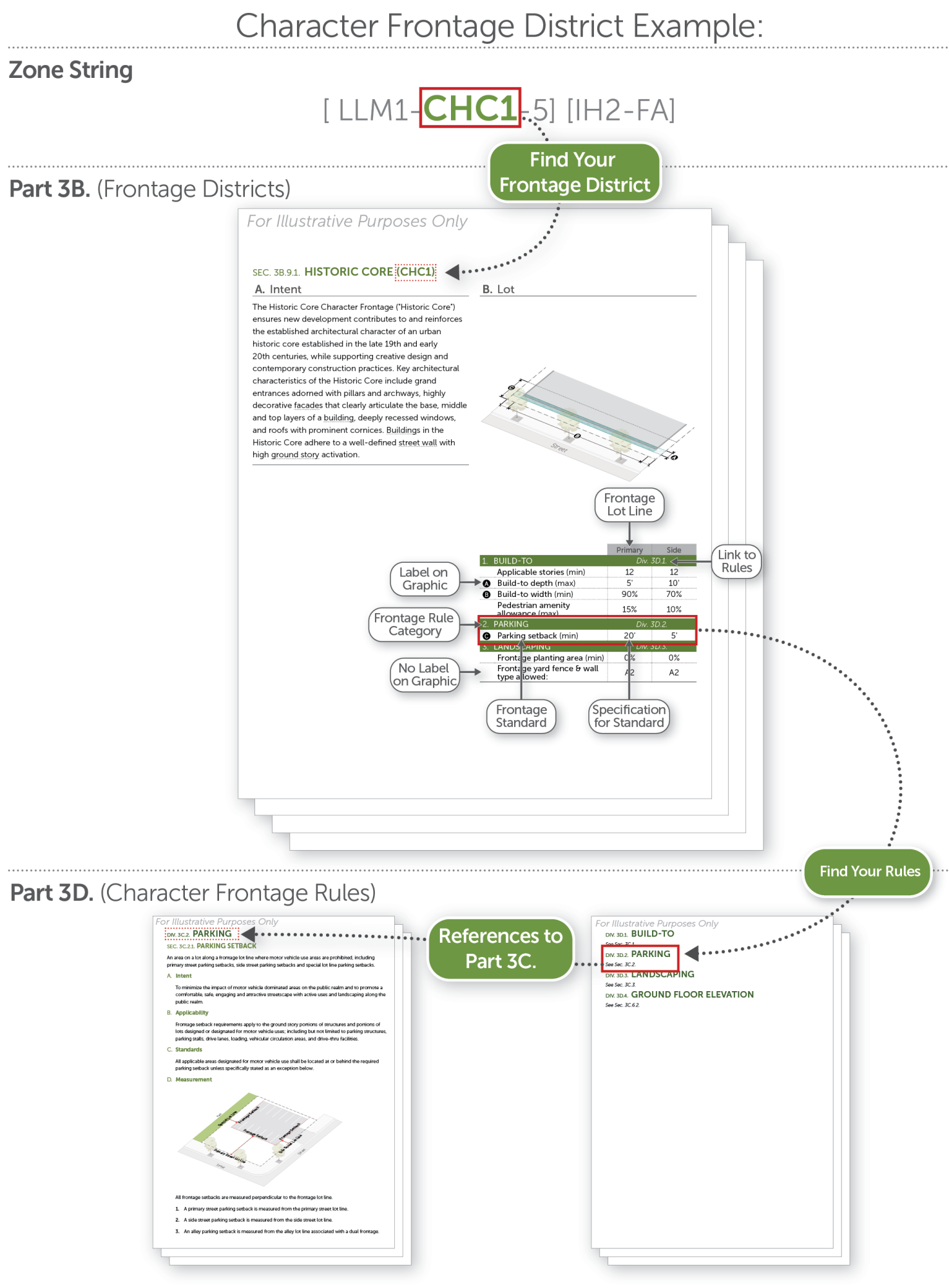
Frontage District standards are outlined in Part 3B. (Frontage Districts). Each Frontage District page identifies the standards specific to that Frontage District.
Each Frontage rule category on a Frontage District page in Part 3B. (Frontage Districts) provides a reference to Part 3C. (General Frontage Rules) or Part 3D. (Character Frontage Rules), where the standards within that rule category are explained in detail. Part 3D. (Character Frontage Rules) may reference Part 3C. (General Frontage Rules) for standards that are common to both Character Frontage Districts and general Frontage Districts. Text in italics below a heading provides a definition of that heading.


Sec. 3A.1.3. Frontage District Diagrams
General
Diagrams and illustrations are provided in this Article (Frontage) to assist users in understanding the purpose and requirements of the text and are not requirements but examples of compliance with a particular standard. In the event a conflict occurs between the text of this Article (Frontage) and any diagram or illustration, the text prevails.
Lot Diagrams

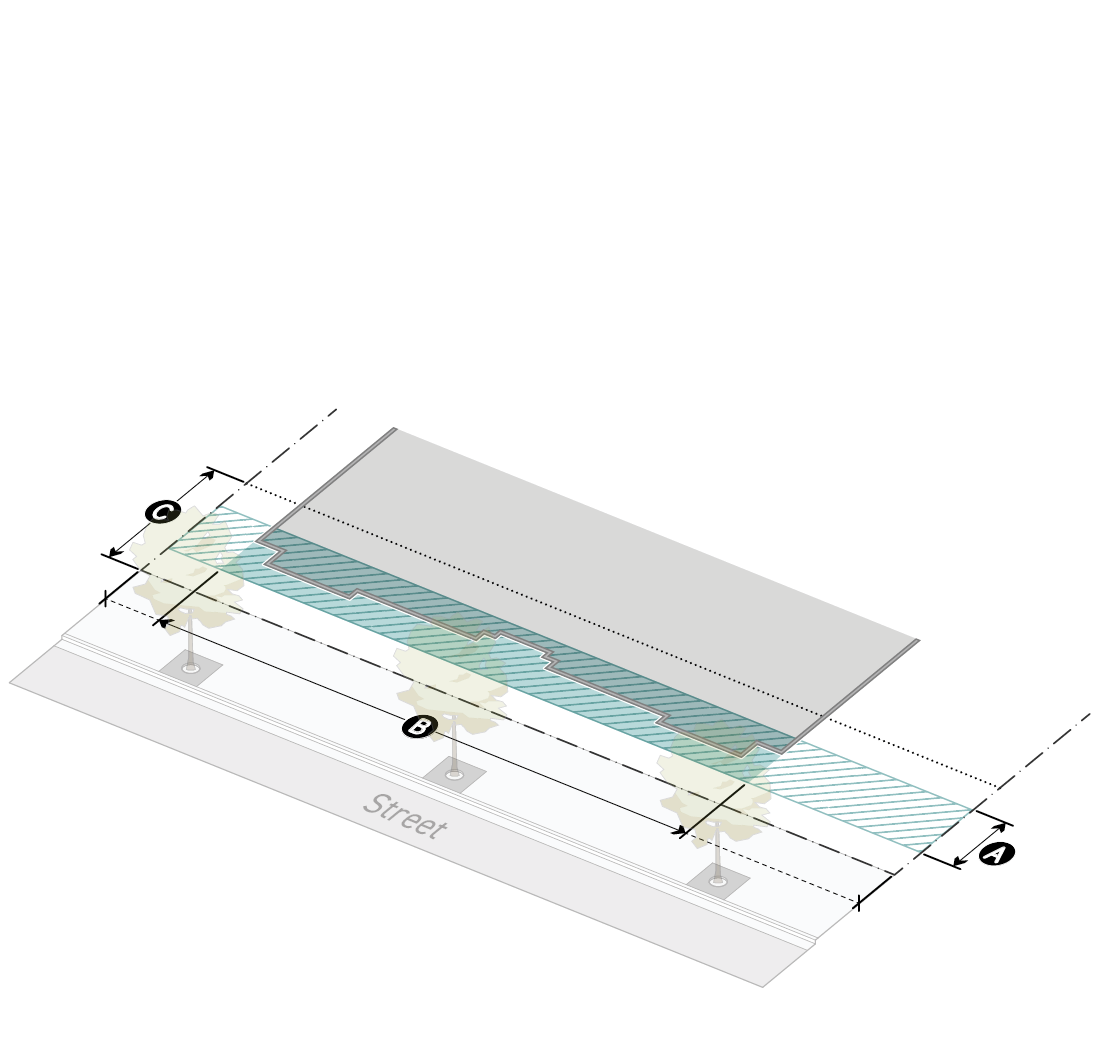
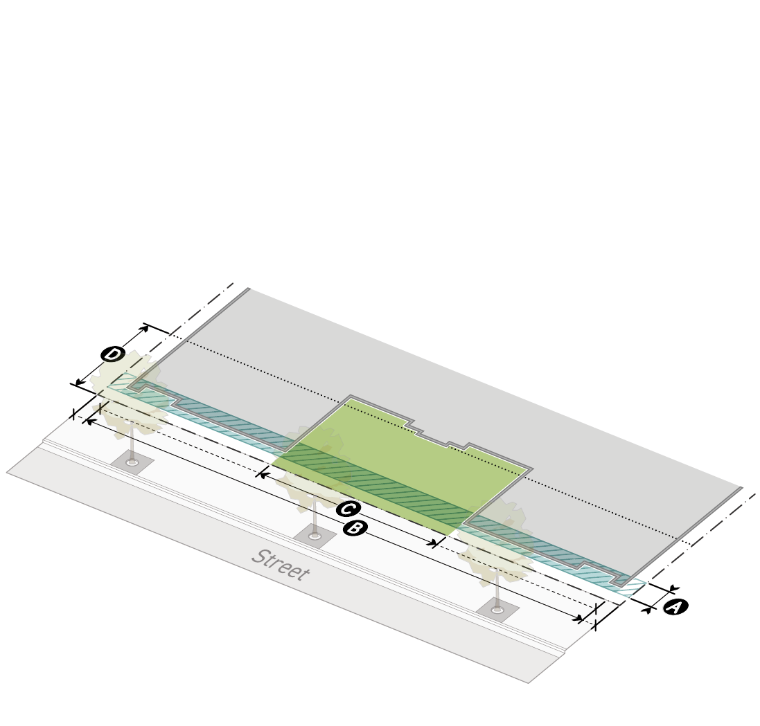
Lot Boundary
This line represents the perimeter of the subject lot, serving as a reference for build-to width.
Build-To Zone
This blue hatched shape represents the area on a lot, near the frontage lot line. Buildings are required to occupy the build-to zone according to the minimum build-to width specified by the applied Frontage District (Part 3B.).
Occupied Build-To Zone
The part of the build-to zone with a blue background representing the width of the build-to zone applied toward build-to width based on location of buildings or location of pedestrian amenity spaces.
Pedestrian Amenity Space
This green shape represents the largest pedestrian amenity space applicable toward the build-to width according to the maximum pedestrian amenity allowance specified by the applied Frontage District (Part 3B.).
Building Footprint
This shape represents the building footprint for the front portion of a lot including the portion of a building occupying the build-to zone, and serves as a reference for build-to width that meets the build-to standards of the applied Frontage District (Part 3B.).
Facade Diagrams

Lot Boundary
This line represents the perimeter of the subject lot, serving as a reference for build-to width.
Pedestrian Amenity Space
This paver-patterned shape represents the pedestrian amenity space shown in the corresponding lot diagram, demonstrating the relationship between pedestrian amenity space requirements, and the standards of the applied Frontage District (Part 3B.).
Story
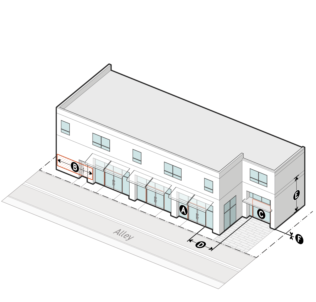
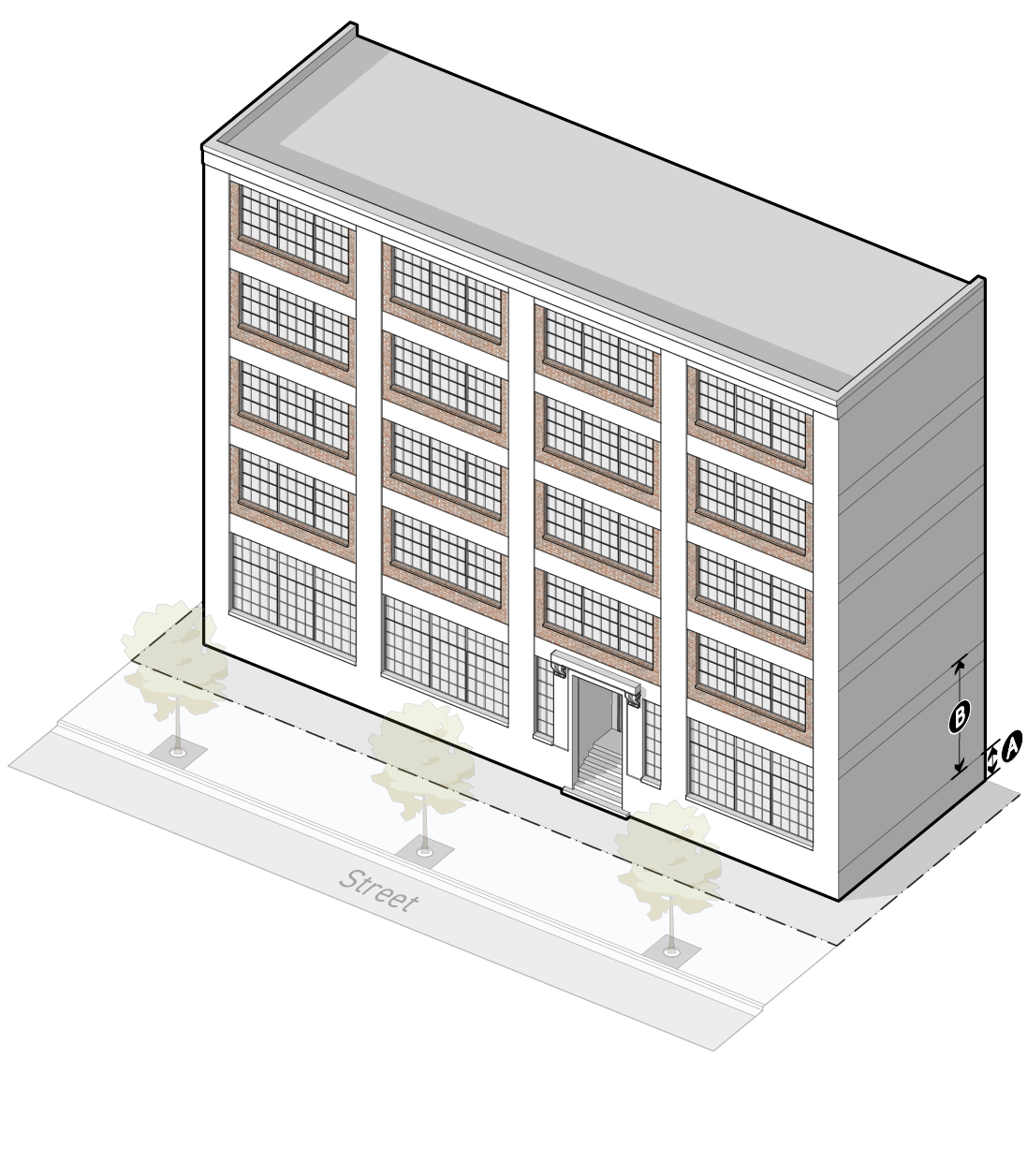
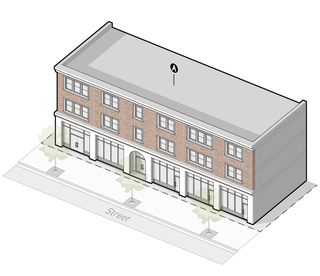
This volume represents a story of a building, serving as a reference for story height and ground floor elevation standards. The volume includes a line at the top and bottom of each story, and an additional line near the top of each story indicating the bottom of a floor plate. The bottom of the floor plate is only depicted on the side of the building.
Transparent Area
This shape represents door and window openings on frontage applicable facades, serving as a reference for transparency standards.
Active Wall Spacing
This red-hatched shape represents one example measurement of active wall spacing, including the regulated facade area between one set of door or window openings. This shape does not represent all applicable facade areas.
Street-Facing Entrance
This red outline represents a street-facing door openings, serving as a reference for street-facing entrance and entrance spacing standards.
Character Frontage Diagrams
Character Frontage Districts (Div. 3B.9.) include a wider variety of diagrams, but use the same approach to representation established by the lot diagrams and facade diagrams. In addition to the elements depicted in lot and frontage diagrams, Character Frontage Districts represent articulation techniques, focal entry features, and exterior materials.
Articulation Techniques
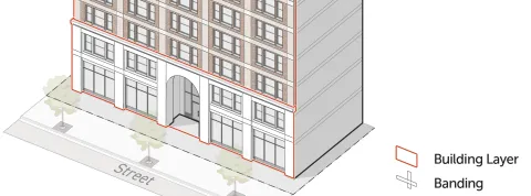
Articulation standards often include a variety of regulatory elements, for example, vertical band articulation and horizontal band articulation, building layers, and articulating elements. While articulating elements are not depicted in Character Frontage District diagrams, building layers are represented with a red outline and banding is represented using a black outline around a translucent white shape.
Focal Entry Features and Exterior Materials

Focal entry features are represented by a dashed red outline surrounding the area on a facade that meets the focal entry feature requirements in the applied Frontage District (Part 3B.).
Primary and secondary exterior materials are represented using a variety of colors and textures to represent one or more of the exterior materials allowed by the applied Frontage District (Part 3B.).


Sec. 3A.1.4. Frontage District Naming Convention
Frontage District names have two components: frontage category and variation number.
Frontage Category
The first component of each Frontage District, frontage categories group all districts with similar characteristics, and are organized as follows:
Drive
Multi-Unit
General
Shopfront
Market
Large Format
Warehouse
Dual
Character
Variation Number
The second component of each Frontage District, a variation number represents the order that the Frontage District falls within this Article (Frontage).
Div. 3A.2. General Rules
Sec. 3A.2.1. Frontage
This Article (Frontage) regulates the portions of a lot and exterior building facades that impact the public realm. Frontage Districts (Part 3B.) help ensure that projects respond to the public realm in a contextually appropriate manner. Frontage Districts range from minimal standards (for example Warehouse Frontages) to a robust set of standards (for example Shopfront Frontages) which require projects to support a high-quality public realm that is active, comfortable, safe, and visually interesting, with strong connections between the public realm and uses inside buildings.
Sec. 3A.2.2. Frontage Applicability
General
All project applications filed after the effective date of this Zoning Code (Chapter 1A) must comply with the Frontage District standards and rules in this Article (Frontage), as further specified in the applicability statement of each Section in Part 3C. (General Frontage Rules) and Part 3D. (Character Frontage Rules). For vested rights, see Sec. 1.4.5. (Vested Rights), and for continuance of existing development, see Sec. 1.4.6. (Continuance of Existing Development).
Applicable Components of Lots, Buildings, & Structures
General
Frontage standards apply only to the applicable facades, portions of a lot, and building depth, as specified in Paragraph 3. (Frontage Applicable Facades) below. Specific Frontage District standards or rules may further limit which components of buildings and lots are required to comply with the standard within Part 3C. (General Frontage Rules) and Part 3D. (Character Frontage Rules).
Frontage Applicable Portions of a Lot
Frontage District standards apply to the following portions of a lot:
Frontage Applicable Facades
Frontage standards apply to the following facades up to the top of the 12th story, unless otherwise specified by the applied Frontage District (Part 3B.):
Frontage Lot Line-Facing Facades

Facades facing a frontage lot line, including street-facing facades, special lot line-facing facades, and when a Dual Frontage District (Div. 3B.8.) is applied.
These facades shall meet the standards specified by the applied Frontage District (Part 3B.) along the frontage lot line that the facade faces (primary street lot line, side street lot line or special lot line).
Lot Line-Facing Facades (Non-Frontage Lot Line)

Lot line-facing facades that do not face a frontage lot line and are:
Located vertically above the top of the fourth story; and
Located 10 feet or more from a common lot line or centerline of an alley, measured horizontally.
Lot line-facing facades (non-frontage lot line) facades shall meet the standards specified by the applied Frontage District (Part 3B.) for the side street lot line.
Pedestrian Amenity Space and Public Amenity Space-Facing Facades

Facades that face a pedestrian amenity space or public amenity space, see Sec. 14.2.6.C. (Pedestrian Amenity & Public Amenity-Facing Facade).
These facades shall meet the standards specified by the applied Frontage District (Part 3B.) for the frontage lot line that the pedestrian amenity space or public amenity space abuts. Where the pedestrian amenity space or public amenity space abuts multiple frontage lot lines, the standards specified for the frontage lot line that abuts the pedestrian amenity space or public amenity space for the greatest length applies.
Frontage Applicable Building Depth
Frontage District standards apply to portions of a building interior within 15 feet of a frontage lot line-facing facade pursuant to Sec. 3A.2.2.B.3.a. (Frontage Lot Line-Facing Facades) or frontage applicable facades facing a pedestrian amenity space or public amenity space pursuant to Sec. 3A.2.2.B.3.c. (Pedestrian Amenity Space and Public Amenity Space-Facing Facades).

Nonconformities
Article 12. (Nonconformities) may provide relief from the requirements of this Article (Frontage) for existing lots, site improvements, buildings and structures, and uses that conformed to the zoning regulations, at the time they were established, but do not otherwise conform to current district standards or use permissions. Unless otherwise specified by Div. 12.3. (Frontage Exceptions), project activities must conform with applicable frontage standards.


Part 3B. Frontage Districts
Div. 3B.1. Drive Frontage Districts
Drive Frontages control the location of vehicular access, require planted front yards, and provide flexible provisions for privacy through a combination of setbacks and frontage yard fence & wall standards.
[Reserved].
Div. 3B.2. Multi-Unit Frontage Districts
Multi-Unit Frontages require higher ground floor elevation, low transparency, and frequent entrance spacing. This allows for greater privacy for tenants located on the ground story while retaining an interplay between the private and public realms. Frequent entrances activate the public realm with pedestrian activity and visual interest.
Sec. 3B.2.1. Multi-Unit 1 (MU1)
A.Lot |
|||

|
|||
|
Primary |
Side |
||
|
1. Build-to |
|||
|
Applicable stories (min) |
2 |
2 |
|
|
A |
Build-to depth (max) |
5' |
5' |
|
B |
Build-to width (min) |
70% |
40% |
|
Pedestrian amenity allowance (max) |
Not Required |
Not Required |
|
|
2. Parking |
|||
|
C |
Parking setback (min) |
20’ |
5' |
|
3. Landscaping |
|||
|
Frontage planting area (min) |
30% |
30% |
|
|
Frontage yard fence & wall type allowed: |
A2 |
A2 |
|
B.Facade |
|||

|
|||
|
Primary |
Side |
||
|
1. Transparency |
|||
|
Transparent area (min) |
|||
|
A |
Ground story |
30% |
30% |
|
b |
Upper stories |
20% |
20% |
|
c |
Active wall spacing (max) |
30’ |
40' |
|
2. Entrances |
|||
|
D |
Street-facing entrance |
Required |
Not Required |
|
E |
Entrance spacing (max) |
50’ |
100' |
|
Entry feature |
Not Required |
Not Required |
|
|
3. Ground Story |
|||
|
F |
Ground story height (min) |
10' |
10' |
|
G |
Ground floor elevation (min/max) |
-2'/5' |
-2'/5' |
Sec. 3B.2.2. Multi-Unit 2 (MU2)
A.Lot |
|||
|
|||
|
Primary |
Side |
||
|
1. Build-to |
|||
|
Applicable stories (min) |
2 |
2 |
|
|
A |
Build-to depth (max) |
10' |
15' |
|
B |
Build-to width (min) |
70% |
40% |
|
Pedestrian amenity allowance (max) |
Not Required |
Not Required |
|
|
2. Parking |
|||
|
C |
Parking setback (min) |
20’ |
5' |
|
3. Landscaping |
|||
|
Frontage planting area (min) |
30% |
30% |
|
|
Frontage yard fence & wall type allowed: |
A2 |
A2 |
|
B.Facade |
|||

|
|||
|
Primary |
Side |
||
|
1. Transparency |
|||
|
Transparent area (min) |
|||
|
A |
Ground story |
30% |
30% |
|
b |
Upper stories |
20% |
20% |
|
c |
Active wall spacing (max) |
30’ |
40' |
|
2. Entrances |
|||
|
D |
Street-facing entrance |
Required |
Not Required |
|
E |
Entrance spacing (max) |
50’ |
100' |
|
Entry feature |
Not Required |
Not Required |
|
|
3. Ground Story |
|||
|
F |
Ground story height (min) |
10' |
10' |
|
G |
Ground floor elevation (min/max) |
-2'/5' |
-2'/5' |
Sec. 3B.2.3. Multi-Unit 3 (MU3)
A.Lot |
|||

|
|||
|
Primary |
Side |
||
|
1. Build-to |
|||
|
Applicable stories (min) |
1 |
1 |
|
|
A |
Build-to depth (max) |
10’ |
15’ |
|
B |
Build-to width (min) |
60% |
40% |
|
Pedestrian amenity allowance (max) |
Not Required |
Not Required |
|
|
2. Parking |
|||
|
C |
Parking setback (min) |
20’ |
5' |
|
3. Landscaping |
|||
|
Frontage planting area (min) |
30% |
30% |
|
|
Frontage yard fence & wall type allowed: |
A3 |
A3 |
|
B.Facade |
|||

|
|||
|
Primary |
Side |
||
|
1. Transparency |
|||
|
Transparent area |
|||
|
A |
Ground story (min) |
12% |
10% |
|
b |
Upper stories (min) |
15% |
12% |
|
c |
Active wall spacing (max) |
20’ |
30' |
|
2. Entrances |
|||
|
D |
Street-facing entrance |
Required |
Not Required |
|
Entrance spacing (max) |
50’ |
100' |
|
|
Entry feature |
Not Required |
Not Required |
|
|
3. Ground Story |
|||
|
e |
Ground story height (min) |
10' |
10' |
|
f |
Ground floor elevation (min/max) |
-2'/5' |
-2'/5' |
Div. 3B.3. General Frontage Districts
General Frontages require moderate to high build-to widths while allowing a wide range of modifications for pedestrian amenity spaces. These Frontage Districts have a moderate transparency requirement with flexible entrance spacing standards while ensuring a high-quality pedestrian environment and providing flexibility for a variety of ground story tenants.
Sec. 3B.3.1. General 1 (G1)
A.Lot |
|||

|
|||
|
Primary |
Side |
||
|
1. Build-to |
|||
|
Applicable stories (min) |
5 |
5 |
|
|
A |
Build-to depth (max) |
10' |
15' |
|
B |
Build-to width (min) |
90% |
70% |
|
C |
Pedestrian amenity allowance (max) |
30% |
20% |
|
2. Parking |
|||
|
D |
Parking setback (min) |
15’ |
5' |
|
3. Landscaping |
|||
|
Frontage planting area (min) |
30% |
30% |
|
|
Frontage yard fence & wall type allowed: |
A2 |
A2 |
|
B.Facade |
|||

|
|||
|
Primary |
Side |
||
|
1. Transparency |
|||
|
Transparent area (min) |
|||
|
A |
Ground story |
50% |
40% |
|
B |
Upper stories |
30% |
30% |
|
C |
Active wall spacing (max) |
25’ |
25’ |
|
2. Entrances |
|||
|
D |
Street-facing entrance |
Required |
Required |
|
E |
Entrance spacing (max) |
75’ |
100' |
|
Entry feature |
Not Required |
Not Required |
|
|
3. Ground Story |
|||
|
F |
Ground story height (min) |
10' |
10' |
|
G |
Ground floor elevation (min/max) |
-2'/5' |
-2'/5' |
Sec. 3B.3.2. General 2 (G2)
A.Lot |
|||

|
|||
|
Primary |
Side |
||
|
1. Build-to |
|||
|
Applicable stories (min) |
1 |
1 |
|
|
A |
Build-to depth (max) |
10’ |
15’ |
|
B |
Build-to width (min) |
70% |
40% |
|
C |
Pedestrian amenity allowance (max) |
20% |
5% |
|
2. Parking |
|||
|
D |
Parking setback (min) |
20’ |
5’ |
|
3. Landscaping |
|||
|
Frontage planting area (min) |
30% |
30% |
|
|
Frontage yard fence & wall type allowed: |
A2 |
A2 |
|
B.Facade |
|||

|
|||
|
Primary |
Side |
||
|
1. Transparency |
|||
|
Transparent area |
|||
|
A |
Ground story (min) |
40% |
30% |
|
B |
Upper stories (min) |
20% |
20% |
|
C |
Active wall spacing (max) |
20’ |
30’ |
|
2. Entrances |
|||
|
D |
Street-facing entrance |
Required |
Not required |
|
Entrance spacing (max) |
50’ |
100’ |
|
|
Entry feature |
Not Required |
Not Required |
|
|
3. Ground Story |
|||
|
e |
Ground story height (min) |
10' |
10' |
|
f |
Ground floor elevation (min/max) |
-2'/5' |
-2'/5' |
Div. 3B.4. Shopfront Frontage Districts
Shopfront Frontages require high build-to widths, high levels of transparency, frequent entrance spacing, and ground floor elevation at or near sidewalk grade. This promotes a legible street wall and activates the public realm with pedestrian activity and visual interest. The at-grade ground floor elevation allows for an increased connection between the interior uses and the pedestrian space.
Sec. 3B.4.1. Shopfront 1 (SH1)
A.Lot |
|||

|
|||
|
Primary |
Side |
||
|
1. Build-to |
|||
|
Applicable stories (min) |
5 |
5 |
|
|
A |
Build-to depth (max) |
5' |
10' |
|
B |
Build-to width (min) |
90% |
70% |
|
C |
Pedestrian amenity allowance (max) |
20% |
10% |
|
2. Parking |
|||
|
D |
Parking setback (min) |
20’ |
5' |
|
3. Landscaping |
|||
|
Frontage planting area (min) |
30% |
30% |
|
|
Frontage yard fence & wall type allowed: |
A2 |
A2 |
|
B.Facade |
|||

|
|||
|
Primary |
Side |
||
|
1. Transparency |
|||
|
Transparent area (min) |
|||
|
A |
Ground story |
70% |
50% |
|
B |
Upper stories |
30% |
30% |
|
C |
Active wall spacing (max) |
15’ |
25' |
|
2. Entrances |
|||
|
D |
Street-facing entrance |
Required |
Required |
|
E |
Entrance spacing (max) |
50’ |
75' |
|
Entry feature |
Not Required |
Not Required |
|
|
3. Ground Story |
|||
|
F |
Ground story height (min) |
16' |
16' |
|
G |
Ground floor elevation (min/max) |
-2'/2' |
-2'/2' |
Sec. 3B.4.2. Shopfront 2 (SH2)
A.Lot |
|||
|
|||
|
Primary |
Side |
||
|
1. Build-to |
|||
|
Applicable stories (min) |
5 |
5 |
|
|
A |
Build-to depth (max) |
5' |
10' |
|
B |
Build-to width (min) |
95% |
70% |
|
C |
Pedestrian amenity allowance (max) |
35% |
10% |
|
2. Parking |
|||
|
D |
Parking setback (min) |
20’ |
5' |
|
3. Landscaping |
|||
|
Frontage planting area (min) |
30% |
30% |
|
|
Frontage yard fence & wall type allowed: |
A2 |
A2 |
|
B.Facade |
|||

|
|||
|
Primary |
Side |
||
|
1. Transparency |
|||
|
Transparent area (min) |
|||
|
A |
Ground story |
60% |
40% |
|
B |
Upper stories |
30% |
30% |
|
C |
Active wall spacing (max) |
15’ |
25' |
|
2. Entrances |
|||
|
D |
Street-facing entrance |
Required |
Required |
|
E |
Entrance spacing (max) |
50’ |
75' |
|
Entry feature |
Not Required |
Not Required |
|
|
3. Ground Story |
|||
|
F |
Ground story height (min) |
16' |
16' |
|
G |
Ground floor elevation (min/max) |
-2'/2' |
-2'/2' |
Sec. 3B.4.3. Shopfront 3 (SH3)
A.Lot |
|||

|
|||
|
Primary |
Side |
||
|
1. Build-to |
|||
|
Applicable stories (min) |
1 |
1 |
|
|
A |
Build-to depth (max) |
5’ |
10’ |
|
B |
Build-to width (min) |
90% |
50% |
|
Pedestrian amenity allowance (max) |
100% |
100% |
|
|
2. Parking |
|||
|
C |
Parking setback (min) |
20’ |
5' |
|
3. Landscaping |
|||
|
Frontage planting area (min) |
30% |
30% |
|
|
Frontage yard fence & wall type allowed: |
A2 |
A2 |
|
B.Facade |
|||

|
|||
|
Primary |
Side |
||
|
1. Transparency |
|||
|
Transparent area (min) |
|||
|
A |
Ground story |
60% |
40% |
|
B |
Upper stories |
20% |
20% |
|
C |
Active wall spacing (max) |
15’ |
30' |
|
2. Entrances |
|||
|
D |
Street-facing entrance |
Required |
Required |
|
E |
Entrance spacing (max) |
50’ |
75' |
|
Entry feature |
Not Required |
Not Required |
|
|
3. Ground Story |
|||
|
F |
Ground story height (min) |
14' |
14' |
|
G |
Ground floor elevation (min/max) |
-2'/2' |
-2'/2' |
Div. 3B.5. Market Frontage Districts
Market Frontages require high build-to widths and frequent entrances integrated as market stalls and shopfront bays. These entry feature options, paired with frequent entrance spacing, activates the public realm with pedestrian activity and visual interest in areas where market stalls are the dominant pattern.
Sec. 3B.5.1. Market 1 (MK1)
A.Lot |
|||

|
|||
|
Primary |
Side |
||
|
1. Build-to |
|||
|
Applicable stories (min) |
5 |
5 |
|
|
A |
Build-to depth (max) |
5' |
10' |
|
B |
Build-to width (min) |
90% |
70% |
|
C |
Pedestrian amenity allowance (max) |
20% |
10% |
|
2. Parking |
|||
|
D |
Parking Setback (min) |
20’ |
5' |
|
3. Landscaping |
|||
|
Frontage planting area (min) |
30% |
30% |
|
|
Frontage yard fence & wall type allowed: |
A2 |
A2 |
|
B.Facade |
|||

|
|||
|
Primary |
Side |
||
|
1. Transparency |
|||
|
Transparent area (min) |
|||
|
A |
Ground story |
60% |
40% |
|
b |
Upper stories |
20% |
20% |
|
c |
Active wall spacing (max) |
15’ |
30' |
|
2. Entrances |
|||
|
D |
Street-facing entrance |
Required |
Required |
|
E |
Entrance spacing (max) |
25’ |
50' |
|
Entry feature |
Required |
Required |
|
|
Options |
•Market Stall •Shopfront Bay |
||
|
3. Ground Story |
|||
|
F |
Ground story height (min) |
16' |
16' |
|
G |
Ground floor elevation (min/max) |
-2'/2' |
-2'/2' |
Div. 3B.6. Large Format Frontage Districts
Large Format Frontages require moderate build-to widths and infrequent entrance spacing. These Frontage Districts are designed to accommodate large tenants and controlled access in a manner that promotes a walkable street edge.
[Reserved]
Div. 3B.7. Warehouse Frontage Districts
The Warehouse Frontages have few standards and allow for a high level of flexibility. These Frontage Districts are designed for freight service. Warehouse Frontages are intended for areas where pedestrian-friendly environments are not a priority.
Sec. 3B.7.1. Warehouse 1 (WH1)
A.Lot |
|||

|
|||
|
Primary |
Side |
||
|
1. Build-to |
|||
|
Not applicable |
|||
|
2. Parking |
|||
|
A |
Parking setback (min) |
5’ |
5' |
|
3. Landscaping |
|||
|
Frontage planting area (min) |
30% |
30% |
|
|
Frontage yard fence & wall type allowed: |
A4 |
A4 |
|
B.Facade |
|||

|
|||
|
Primary |
Side |
||
|
1. Transparency |
|||
|
Not applicable |
|||
|
2. Entrances |
|||
|
a |
Street-facing entrance |
Required |
Not Required |
|
Entrance spacing (max) |
Not Required |
Not Required |
|
|
Entry feature |
Not Required |
Not Required |
|
|
3. Ground Story |
|||
|
Not applicable |
|||
Div. 3B.8. Dual Frontage Districts
The Dual Frontages are required to address primary, side, and special frontage lot lines. This allows for activation of the frontage lot line with increased standards.
Sec. 3B.8.1. Alley Market (AL1)
A.Lot |
||||

|
||||
|
Special |
Primary |
Side |
||
|
1. Build-to |
||||
|
Applicable stories (min) |
5 |
5 |
5 |
|
|
A |
Build-to depth (max) |
10' |
5' |
10' |
|
B |
Build-to width (min) |
90% |
90% |
70% |
|
Pedestrian amenity allowance (max) |
10% |
20% |
10% |
|
|
2. Parking |
||||
|
C |
Parking Setback (min) |
15' |
20’ |
5' |
|
3. Landscaping |
||||
|
Frontage planting area (min) |
10% |
20% |
30% |
|
|
Frontage yard fence & wall type allowed: |
A1 |
A2 |
A2 |
|
B.Facade |
||||

|
||||
|
Special |
Primary |
Side |
||
|
1. Transparency |
||||
|
Transparent area (min) |
||||
|
Ground story |
n/a |
60% |
40% |
|
|
Upper stories |
n/a |
20% |
20% |
|
|
A |
Active wall spacing (max) |
25' |
15’ |
30' |
|
2. Entrances |
||||
|
B |
Street-facing entrance |
Required |
Required |
Required |
|
C |
Entrance spacing (max) |
25' |
25’ |
50' |
|
Entry feature |
Required |
Required |
Required |
|
|
Options |
•Shopfront bay •Market stall |
|||
|
3. Ground Story |
||||
|
D |
Ground story height (min) |
16' |
16' |
16' |
|
E |
Ground floor elevation (min/max) |
-1/1' |
-2/2' |
-2/2' |
Sec. 3B.8.2. Alley Shopfront (AL2)
A.Lot |
||||

|
||||
|
Special |
Primary |
Side |
||
|
1. Build-to |
||||
|
Applicable stories (min) |
5 |
5 |
5 |
|
|
A |
Build-to depth (max) |
10' |
5' |
10' |
|
B |
Build-to width (min) |
70% |
95% |
70% |
|
C |
Pedestrian amenity allowance (max) |
15% |
35% |
10% |
|
2. Parking |
||||
|
D |
Parking Setback (min) |
15' |
20’ |
5' |
|
3. Landscaping |
||||
|
Frontage planting area (min) |
10% |
20% |
30% |
|
|
Frontage yard fence & wall type allowed: |
A1 |
A2 |
A2 |
|
B.Facade |
||||
|
||||
|
Special |
Primary |
Side |
||
|
1. Transparency |
||||
|
Transparent area (min) |
||||
|
A |
Ground story |
60% |
60% |
40% |
|
Upper stories |
n/a |
30% |
30% |
|
|
B |
Active wall spacing (max) |
25' |
15’ |
25' |
|
2. Entrances |
||||
|
C |
Street-facing entrance |
Required |
Required |
Required |
|
D |
Entrance spacing (max) |
25' |
50’ |
75' |
|
Entry feature |
Required |
n/a |
n/a |
|
|
Options |
•Storefront bay |
|||
|
3. Ground Story |
||||
|
E |
Ground story height (min) |
16' |
16' |
16' |
|
F |
Ground floor elevation (min/max) |
-1/1' |
-2/2' |
-2/2' |
Sec. 3B.8.3. Greenway 1 (GW1)
A.Lot |
||||

|
||||
|
Special |
Primary |
Side |
||
|
1. Build-to |
||||
|
Applicable stories (min) |
1 |
1 |
1 |
|
|
A |
Build-to depth (max) |
25’ |
25’ |
25’ |
|
B |
Build-to width (min) |
70% |
70% |
40% |
|
C |
Pedestrian amenity allowance (max) |
100% |
20% |
5% |
|
2. Parking |
||||
|
D |
Parking Setback (min) |
10’ |
5’ |
5’ |
|
3. Landscaping |
||||
|
Frontage planting area (min) |
75% |
30% |
30% |
|
|
Frontage yard fence & wall type allowed: |
A3 |
A3 |
A4 |
|
B.Facade |
||||

|
||||
|
Special |
Primary |
Side |
||
|
1. Transparency |
||||
|
Transparent area (min) |
||||
|
A |
Ground story |
20% |
20% |
20% |
|
B |
Upper stories |
20% |
20% |
20% |
|
C |
Active wall spacing (max) |
30’ |
20’ |
30’ |
|
2. Entrances |
||||
|
D |
Street-facing entrance |
Required |
Required |
Required |
|
Entrance spacing (max) |
75’ |
75’ |
100’ |
|
|
Entry feature |
Not required |
Not required |
Not required |
|
|
3. Ground Story |
||||
|
E |
Ground story height (min) |
14’ |
14’ |
14’ |
|
Ground floor elevation (min/max) |
-2’/5’ |
-2’/5’ |
-2’/5’ |
|
Div. 3B.9. Character Frontage Districts
Character Frontages provide standards for facade articulation, entry features, window design, siding materials, and roof form, in order to reinforce the prevailing architectural characteristics of the city’s historically and culturally significant neighborhoods and districts.
Sec. 3B.9.1. Historic Core (CHC1)
A.Intent |
|
The Historic Core Character Frontage ("Historic Core") ensures new development contributes to and reinforces the established architectural character of an urban historic core established in the late 19th and early 20th centuries, while supporting creative design and contemporary construction practices. Key architectural characteristics of the Historic Core include grand entrances adorned with pillars and archways, highly decorative facades that clearly articulate the base, middle and top layers of a building, deeply recessed windows, and roofs with prominent cornices. Buildings in the Historic Core adhere to a well-defined street wall with high ground story activation. |
B.Lot |
|||

|
|||
|
Primary |
Side |
||
|
1. Build-to |
|||
|
Applicable stories (min) |
12 |
12 |
|
|
A |
Build-to depth (max) |
5' |
10' |
|
B |
Build-to width (min) |
90% |
70% |
|
Pedestrian amenity allowance (max) |
15% |
10% |
|
|
2. Parking |
|||
|
C |
Parking setback (min) |
20' |
5' |
|
3. Landscaping |
|||
|
Frontage planting area (min) |
0% |
0% |
|
|
Frontage yard fence & wall type allowed: |
A2 |
A2 |
|
C.Stories |
|||

|
|||
|
Primary |
Side |
||
|
1. Ground floor elevation |
|||
|
a |
Ground floor elevation (min/max) |
-2'/2' |
-2'/2' |
|
2. Story Height |
|||
|
b |
Ground story height (min) |
16' |
16' |
D.Facade |
|||

|
|||
|
Primary |
Side |
||
|
1. Articulation |
|||
|
Applicable stories (min) |
First 12 |
First 12 |
|
|
A |
Base, middle & top articulation |
Required |
Required |
|
b |
Horizontal band articulation |
Required |
Required |
|
c |
Vertical band articulation |
Required |
Required |
|
Spacing (min/max) |
15'/30' |
15'/30' |
|
|
2. Features |
|||
|
Applicable stories (min) |
12 |
12 |
|
|
Restricted features |
|||
|
Projecting balcony |
Prohibited |
Prohibited |
|
E.Doors |
|||

|
|||
|
Primary |
Side |
||
|
1. Entrances |
|||
|
A |
Street-facing entrance |
Required |
Required |
|
b |
Entrance spacing (max) |
50' |
50' |
|
Entry feature |
Required |
Required |
|
|
Options |
•Recessed entry •Storefront bay |
||
|
c |
Focal entry feature |
1 |
0 |
F.Windows |
|||

|
|||
|
Primary |
Side |
||
|
1. Transparency |
|||
|
Applicable stories (min) |
First 12 |
First 12 |
|
|
A |
Ground story (min/max) |
50%/80% |
50%/80% |
|
Active wall spacing (max) |
15' |
15' |
|
|
Window recession (min) |
12" |
12" |
|
|
Bulkhead |
Required |
Required |
|
|
Horizontal sliding windows |
Prohibited |
Prohibited |
|
|
Vinyl windows |
Prohibited |
Prohibited |
|
|
B |
Upper stories (min/max) |
30%/80% |
30%/80% |
|
Window recession (min) |
6" |
6" |
|
|
Sill |
Required |
Required |
|
|
Horizontal sliding windows |
Prohibited |
Prohibited |
|
G.Cladding |
||

|
||
|
1. Exterior Materials |
||
|
Applicable stories (min) |
First 12 |
|
|
A |
Principal material coverage (min) |
70% |
|
Options |
•Brick •Solid stone •Concrete •Metal •Glazed tile |
|
|
B |
Accessory material coverage (max) |
30% |
|
Options |
•Brick •Solid stone •Concrete •Metal •Wood •Glazed tile |
|
|
Number of accessory materials (max) |
2 |
|
H.Roof |
|
|
1. Roof design |
|
|
Not applicable |
|
Sec. 3B.9.2. Daylight Factory (CDF1)
A.Intent |
|
The Daylight Factory Character Frontage ensures new development reinforces the prevailing architectural characteristics of industrial districts established in the early 20th century, while supporting creative design and contemporary construction practices. Warehouse and factory buildings in these industrial districts are characterized by large, symmetrical windows that extend nearly a full story in height, high ceilings on each story, and brick and masonry facade materials. Facades are articulated to establish uniformity through horizontal repetition. |
B.Lot |
|||

|
|||
|
Primary |
Side |
||
|
1. Build-to |
|||
|
Applicable stories (min) |
3 |
3 |
|
|
A |
Build-to depth (max) |
5' |
10' |
|
B |
Build-to width (min) |
90% |
70% |
|
Pedestrian amenity allowance (max) |
30% |
30% |
|
|
2. Parking |
|||
|
C |
Parking setback (min) |
20' |
5' |
|
3. Landscaping |
|||
|
Frontage planting area (min) |
30% |
30% |
|
|
Frontage yard fence & wall type allowed: |
A2 |
A2 |
|
C.Stories |
|||
|
|||
|
Primary |
Side |
||
|
1. Ground floor elevation |
|||
|
a |
Ground floor elevation (min/max) |
-2'/5' |
-2'/5' |
|
2. Story Height |
|||
|
b |
Ground story height (min) |
16' |
16' |
D.Facade |
|||

|
|||
|
Primary |
Side |
||
|
1. Articulation |
|||
|
Applicable stories (min) |
First 3 |
First 3 |
|
|
A |
Vertical band articulation |
Required |
Required |
|
Spacing (min/max) |
20'/30' |
20'/30' |
|
|
2. Features |
|||
|
Not applicable |
|||
E.Doors |
|||

|
|||
|
Primary |
Side |
||
|
1. Entrances |
|||
|
A |
Street-facing entrance |
Required |
Required |
|
b |
Entrance spacing (max) |
100' |
100' |
|
Entry feature |
Required |
Required |
|
|
Options |
•Recessed entry •Storefront bay |
||
|
c |
Focal entry feature |
1 |
1 |
F.Windows |
|||

|
|||
|
Primary |
Side |
||
|
1. Transparency |
|||
|
Applicable stories (min) |
First 3 |
First 3 |
|
|
A |
Ground story (min/max) |
50%/80% |
50%/80% |
|
Active wall spacing (max) |
15' |
25' |
|
|
Window recession (min) |
9" |
9" |
|
|
Horizontal sliding windows |
Prohibited |
Prohibited |
|
|
B |
Upper stories (min/max) |
40%/70% |
30%/70% |
|
Window recession (min) |
6" |
6" |
|
|
Sill |
Required |
Required |
|
|
Horizontal sliding windows |
Prohibited |
Prohibited |
|
G.Cladding |
||

|
||
|
1. Exterior Materials |
||
|
Applicable stories (min) |
First 3 |
|
|
A |
Principal material coverage (min) |
70% |
|
Options |
•Brick •Solid stone •Concrete •Metal •Wood |
|
|
B |
Accessory material coverage (max) |
30% |
|
Options |
•Brick •Solid stone •Concrete •Metal •Wood |
|
|
Number of accessory materials (max) |
3 |
|
H.Roof |
|
|
1. Roof design |
|
|
Not applicable |
|
Sec. 3B.9.3. Daylight Factory / River (CDR1)
A.Intent |
|
The Daylight Factory / River Character Frontage provides standards intended to support the activation of the Los Angeles River as a public amenity while reinforcing the prevailing architectural characteristics of industrial districts established in the early 20th century along the River, and supporting creative design and contemporary construction practices. Warehouse and factory buildings in these riverside industrial districts are characterized by large, symmetrical windows that extend nearly a full story in height, high ceilings on each story, and brick and masonry facade materials. Facades are articulated to establish uniformity through horizontal repetition. |
B.Lot |
||||

|
||||
|
Primary |
Side |
Special |
||
|
1. Build-to |
||||
|
Applicable stories (min) |
3 |
3 |
3 |
|
|
A |
Build-to depth (max) |
5' |
10' |
20' |
|
B |
Build-to width (min) |
90% |
70% |
70% |
|
Pedestrian amenity allowance (max) |
30% |
30% |
40% |
|
|
2. Parking |
||||
|
C |
Parking setback (min) |
20' |
5' |
20' |
|
3. Landscaping |
||||
|
Frontage planting area (min) |
5% |
5% |
75% |
|
|
Frontage yard fence & wall type allowed: |
A2 |
A2 |
A3 |
|
C.Stories |
||||

|
||||
|
Primary |
Side |
Special |
||
|
1. Ground floor elevation |
||||
|
a |
Ground floor elevation (min/max) |
-2'/5' |
-2'/5' |
-2'/5' |
|
2. Story Height |
||||
|
b |
Ground story height (min) |
16' |
16' |
16' |
D.Facade |
||||

|
||||
|
Primary |
Side |
Special |
||
|
1. Articulation |
||||
|
Applicable stories (min) |
First 3 |
First 3 |
First 3 |
|
|
A |
Vertical band articulation |
Required |
Required |
Required |
|
Spacing (min/max) |
20'/30' |
20'/30' |
20'/30' |
|
|
2. Features |
||||
|
Not applicable |
||||
E.Doors |
||||

|
||||
|
Primary |
Side |
Special |
||
|
1. Entrances |
||||
|
A |
Street-facing entrance |
Required |
Required |
Required |
|
b |
Entrance spacing (max) |
100' |
100' |
100' |
|
Entry feature |
Required |
Required |
n/a |
|
|
Options |
•Recessed entry •Storefront bay |
|||
|
c |
Focal entry feature |
1 |
1 |
n/a |
F.Windows |
||||

|
||||
|
Primary |
Side |
Special |
||
|
1. Transparency |
||||
|
Applicable stories (min) |
First 3 |
First 3 |
First 3 |
|
|
A |
Ground story |
50%/80% |
50%/80% |
30%/80% |
|
Active wall spacing (max) |
15' |
25' |
25' |
|
|
Window recession (min) |
9" |
9" |
9" |
|
|
Horizontal sliding windows |
Prohibited |
Prohibited |
Prohibited |
|
|
B |
Upper stories |
40%/70% |
30%/70% |
30%/70% |
|
Window recession (min) |
6" |
6" |
6" |
|
|
Sill |
Required |
Required |
Required |
|
|
Horizontal sliding windows |
Prohibited |
Prohibited |
Prohibited |
|
G.Cladding |
||

|
||
|
1. Exterior Materials |
||
|
Applicable stories (min) |
First 3 |
|
|
A |
Principal material coverage (min) |
70% |
|
Options |
•Brick •Solid stone •Concrete •Metal •Wood |
|
|
B |
Accessory material coverage (max) |
30% |
|
Options |
•Brick •Solid stone •Concrete •Metal •Wood |
|
|
Number of accessory materials (max) |
3 |
|
H.Roof |
|
|
1. Roof design |
|
|
Not applicable |
|
Sec. 3B.9.4. Character Commercial 1 (CC1)
A.Intent |
|
The Character Commercial 1 Frontage provides standards intended to reinforce the prevailing architectural characteristics of streetcar oriented commercial districts established during the late 19th and early 20th centuries. Such districts are characterized by one and two story brick buildings containing rows of small storefronts that were originally built to serve some of the city’s earliest neighborhoods. Key features include the decorative application of brick, shopfront and roofline cornices, recessed entrances, and large shopfront windows. Buildings that retain the qualities of early commercial districts adhere to a well-defined street wall with high ground floor activation. By providing a set of targeted design standards that regulate these key features the Character Commercial 1 Frontage ensures that new development contributes to the established architectural character of the city’s earliest commercial districts. |
B.Lot |
|||

|
|||
|
Primary |
Side |
||
|
1. Build-to |
|||
|
Applicable stories (min) |
2 |
2 |
|
|
A |
Build-to depth (max) |
5' |
10' |
|
B |
Build-to width (min) |
90% |
70% |
|
Pedestrian amenity allowance (max) |
15% |
10% |
|
|
2. Parking |
|||
|
C |
Parking setback (min) |
20' |
5' |
|
3. Landscaping |
|||
|
Frontage planting area (min) |
0% |
0% |
|
|
Frontage yard fence & wall type allowed: |
A1 |
A1 |
|
C.Stories |
|||

|
|||
|
Primary |
Side |
||
|
1. Ground floor elevation |
|||
|
a |
Ground floor elevation (min/max) |
-2'/2' |
-2'/2' |
|
2. Story Height |
|||
|
b |
Ground story height (min) |
14' |
14' |
D.Facade |
|||

|
|||
|
Primary |
Side |
||
|
1. Articulation |
|||
|
Applicable stories (min) |
First 2 |
First 2 |
|
|
A |
Base-top articulation |
Required |
Required |
|
2. Features |
|||
|
Not applicable |
|||
E.Doors |
|||

|
|||
|
Primary |
Side |
||
|
1. Entrances |
|||
|
A |
Street-facing entrance |
Required |
Required |
|
b |
Entrance spacing (max) |
50' |
50' |
|
Entry feature |
Required |
Required |
|
|
Options |
•Recessed entry •Covered entry •Storefront bay |
||
|
c |
Focal entry feature |
1 |
0 |
F.Windows |
|||

|
|||
|
Primary |
Side |
||
|
1. Transparency |
|||
|
Applicable stories (min) |
First 2 |
First 2 |
|
|
A |
Ground story (min/max) |
50%/70% |
50%/70% |
|
Active wall spacing (max) |
20' |
30' |
|
|
Window recession (min) |
6' |
6' |
|
|
Bulkhead |
Required |
Required |
|
|
B |
Upper stories (min/max) |
30%/50% |
30%/60% |
|
Window recession (min) |
3" |
3" |
|
G.Cladding |
||

|
||
|
1. Exterior Materials |
||
|
Applicable stories (min) |
First 2 |
|
|
A |
Principal material coverage (min) |
70% |
|
Exterior material options: |
•Brickwork •Stonework •Glazed tile •Concrete |
|
|
B |
Accessory material coverage (max) |
30% |
|
Exterior material options: |
•Brickwork •Stonework •Concrete •Metal •Wood •Glazed tile |
|
|
Number of accessory materials (max) |
2 |
|
H.Roof |
|||
|
|||
|
Primary |
Side |
||
|
1. Roof Design |
|||
|
A |
Roof form (options) |
•Flat |
|
Sec. 3B.9.5. Character Residential 1 (CR1)
A.Intent |
|
The Character Residential 1 Frontage provides standards intended to reinforce the prevailing architectural characteristics of the city’s residential neighborhoods established throughout the late 19th and early 20th centuries. Such neighborhoods are characterized by an eclectic mix of residential architecture, including Late-Victorian, Queen Anne, and Craftsman architectural styles. Together these styles share some unifying characteristics, such as building forms articulated by a prominent pitched roof or series of pitched roofs, entries featuring a covered front porch, and textured exterior wall surfaces of lap or shingle siding. Other common neighborhood characteristics include homes setback behind a front yard and parking areas hidden from view behind the main building. By providing a set of targeted design standards that regulate these key features the Character Residential 1 Frontage ensures that new development contributes to the established architectural character of the City’s earliest residential neighborhoods. |
B.Lot |
|||

|
|||
|
Primary |
Side |
||
|
1. Build-to |
|||
|
Applicable stories (min) |
3 |
3 |
|
|
A |
Build-to depth (max) |
10' |
15' |
|
B |
Build-to width (min) |
50% |
40% |
|
Pedestrian amenity allowance (max) |
None |
None |
|
|
2. Parking |
|||
|
C |
Parking setback (min) |
20' |
5' |
|
3. Landscaping |
|||
|
Frontage planting area (min) |
30% |
30% |
|
|
Frontage yard fence & wall type allowed: |
A2 |
A2 |
|
C.Stories |
|||

|
|||
|
Primary |
Side |
||
|
1. Ground floor elevation |
|||
|
a |
Ground floor elevation (min/max) |
1.5'/5' |
1.5'/5' |
|
2. Story Height |
|||
|
b |
Ground story height (min) |
Not required |
Not required |
D.Facade |
|||
|
Primary |
Side |
||
|
1. Articulation |
|||
|
Not applicable |
|||
|
2. Features |
|||
|
Not applicable |
|||
E.Doors |
|||

|
|||
|
Primary |
Side |
||
|
1. Entrances |
|||
|
A |
Street-facing entrance |
Required |
Not required |
|
Entrance spacing (max) |
50' |
50' |
|
|
Entry feature |
Required |
Not required |
|
|
Options |
•Porch |
||
|
Focal entry feature |
Not required |
Not required |
|
F.Windows |
|||

|
|||
|
Primary |
Side |
||
|
1. Transparency |
|||
|
Applicable stories |
First 3 |
First 3 |
|
|
A |
Ground story (min/max) |
10%/35% |
7%/35% |
|
Active wall spacing (max) |
10' |
15' |
|
|
Window recession (min) |
1" |
1" |
|
|
B |
Upper stories (min/max) |
10%/35% |
7%/35% |
|
Window recession (min) |
1" |
1" |
|
G.Cladding |
|||
|
Primary |
Side |
||
|
1. Exterior Materials |
|||
|
Not applicable |
|||
H.Roof |
||

|
||
|
1. Roof Design |
||
|
A |
Roof form (options) |
•Pitched |
|
Roof Overhang (min) |
10' |
|
Part 3C. General Frontage Rules
Div. 3C.1. Build-To
Sec. 3C.1.1. Applicable Stories
Applicable stories is defined as the number of stories that are required to meet build-to standards.
Intent
The intent of the standards of this Section (Applicable Stories) is to ensure that ground stories of buildings, and upper stories where appropriate, are located in a consistent manner along the street.
Applicability
Applicable stories standards apply to new construction of any portion of a building, or a whole building. When the applicable stories standards apply, the standards apply to any part of the building that is required to meet the standards of Sec. 3C.1.2. (Build-To Depth) and the standards of Sec. 3C.1.3. (Build-To Width).
Standards
Where minimum applicable stories are required, build-to standards apply to the ground story and any additional story provided on a lot, up to, and including, the minimum build-to applicable stories.

Measurement
For measuring height in stories, see Sec. 2C.4.3. (Height in Stories).
Relief
A reduction of one story from the number of applicable stories may be granted in accordance with Sec. 13B.5.2. (Adjustment).
A reduction in number of applicable stories may be granted as a variance in accordance with Sec. 13B.5.3. (Variance).

Sec. 3C.1.2. Build-To Depth
Build-to depth is defined as the depth of the build-to zone starting at the minimum building setback and continuing inward for the maximum build-to depth for the full width of the lot.
Intent
The intent of the standards of this Section (Build-To-Depth) is to regulate buildings along the public realm and to create a consistent street wall.
Applicability
Build-to depth standards apply to new construction. When build-to depth standards apply, they apply to all portions of buildings required to satisfy the standards of Sec. 3C.1.3. (Build-To Width) and the standards of Sec. 3C.1.1. (Applicable Stories).
Standards
The build-to zone shall be no deeper than the maximum build-to depth of the applied Frontage District (Part 3B.).
Buildings shall occupy the build-to zone for at least the minimum required build-to width.
Once the minimum build-to width standard has been satisfied, buildings and structures may occupy the area behind the build-to zone.
On a corner lot where intersecting frontage lot lines have build-to requirements, a building shall occupy the portion of the lot area where the build-to zones of the two intersecting frontage lot lines overlap, as described below:
The building shall occupy the build-to zones for both frontage lot lines for a minimum of 30 feet from the corner. This building width counts toward the required build-to width for both frontage lot lines.
This standard does not apply when a pedestrian amenity space occupies some portion of the area of overlap and is being used as a pedestrian amenity allowance. See Sec. 3C.1.4. (Pedestrian Amenity Allowance).

Measurement
The build-to depth is measured perpendicular to the frontage lot line starting from the minimum building setback and continuing inward away from the frontage lot line.
Where a lot includes an easement that abuts the frontage lot line and the easement is deeper than the minimum building setback, the applicant may choose to measure the required build-to depth from the interior edge of the easement rather than the lot line.

For a lot affected by a public access easement, see Sec. 14.2.17.B.3. (Build-To Depth).
Exceptions
To preserve existing trees that meet minimum size requirements for a small species tree, the Department may increase the build-to depth beyond the maximum allowed by the applied Frontage District to the minimum depth necessary to protect the tree, but by no more than 30 feet pursuant to Sec. 13B.3.1. (Administrative Review).
See Sec. 12.3.1. (Build-To Exceptions).

Relief
An increase in build-to depth of 20 percent may be granted in accordance with Sec. 13B.5.2. (Adjustment).
A deviation from maximum build-to depth may be granted as a variance in accordance with Sec. 13B.5.3. (Variance).


Sec. 3C.1.3. Build-To Width
Build-to width is defined as the cumulative building width that shall occupy the build-to zone, relative to the width of the lot at the frontage lot line.
Intent
The intent of the standards of this Section (Build-To-Width) is to ensure that buildings enclose the public realm with a legible and consistent street wall, spatially defining an outdoor room, and to promote a strong visual and physical connection between uses inside buildings and the public realm.
Applicability
Build-to width standards apply to new construction and are subject to the following:
Where a minimum height is specified in the applied Form District (Part 2B.), build-to width standards apply to all above-grade stories up to the minimum height in stories standard in accordance with Sec. 2C.4.3. (Height in Stories).

Where an applicable stories standard exists, build-to width standards apply to all stories located above-grade up to the applicable stories.

Where both an applicable stories standard and a minimum height standard are specified, build-to width standards apply to whichever standard requires the greatest number of stories located in the build-to zone.
Where no applicable stories standard is specified in the applied Frontage District (Part 3B.) and no minimum height standard is specified in the applied Form District (Part 2B.), build-to width standards apply only to the ground story.
Standards
Building(s) shall occupy the build-to zone for a cumulative width no less than that specified by the applied Frontage District (Part 3B.).
On a corner lot, a chamfered corner no more than 20 feet in width along both street lot lines qualifies as building width in the build-to zone for all applicable stories even where it extends outside of the build-to zone. Chamfered corner width is measured parallel to the frontage lot line.

Portions of building width providing motor vehicle access to a motor vehicle use area through the ground story of a building do not qualify as building width in the build-to zone.

When build-to width is specified as “building-based”, the build-to zone shall be occupied by buildings for not less than 50 percent of the width of the building having the greatest total floor area on the lot.
Measurement
The build-to width is a percentage measured as the sum of the widths of all portions of buildings occupying the build-to zone divided by the total lot width.

Building width is measured parallel to the frontage lot line. For measuring building width on a lot with a curved or irregular lot line, see Sec. 14.2.14. (Irregular Lot Lines).
Lot width is measured along the frontage lot line. For measuring width of a lot with a curved or irregular lot line, see Sec. 14.2.14. (Irregular Lot Lines).
Exceptions
Pedestrian amenity space counts toward required minimum build-to width in accordance with Sec.3C.1.4. (Pedestrian Amenity Allowance).
A building break that includes an open space meeting the design standards for pedestrian amenity space in Sec. 2C.3.3.C.2. (Pedestrian Amenity Space) counts toward the minimum build-to width required by the applied Frontage District (Part 3B.) according to Sec. 3C.1.4. (Pedestrian Amenity Allowance).
Where vehicle access is taken through the frontage lot line based on the automobile access package in Sec. 4C.2.1. (Automobile Access Packages) as specified by the applied Development Standards District (Part 4B.), and providing vehicle access prevents a building from achieving the required build-to width, a reduced build-to width may be allowed. However, the portion of the lot in the build-to zone used for vehicle access shall be no wider than the minimum required drive aisle width plus an additional four feet of width for clearance. See Div. 4C.2. (Automobile Access).
See Sec. 12.3.1. (Build-To Exceptions).

Relief
Up to a 10 percent reduction to the total required width of a building occupying the build-to zone may be granted in accordance with Sec. 13B.5.2. (Adjustment).
A reduced minimum build-to width may be granted as a variance in accordance with Sec. 13B.5.3. (Variance).


Sec. 3C.1.4. Pedestrian Amenity Allowance
Pedestrian amenity allowance is defined as the width of pedestrian amenity space in the build-to zone that can be counted toward the build-to width requirement.
Intent
The intent of the standards of this Section (Pedestrian Amenity Allowance) is to promote the creation of active, human-scale outdoor spaces as an extension of the sidewalk, providing visual interest and vitality to the amenity space as well as the public realm. The pedestrian amenity allowance provides flexibility to building and site design while maintaining standards essential for ensuring all projects contribute to defining a consistent and legible street wall.
Applicability
Pedestrian amenity allowance standards apply to new construction subject to a pedestrian amenity allowance maximum in the applied Frontage District (Part 3B.).
Pedestrian amenity allowance standards apply to all portions of a building or structure required to meet the standards of Sec. 3C.1.3. (Build-To Width) and Sec. 14.2.6.C. (Pedestrian Amenity & Public Amenity-Facing Facades), and portions of the lot between the building and the frontage lot line for the width of the pedestrian amenity space provided.
Standards
Where the applied Frontage District (Part 3B.) specifies a pedestrian amenity allowance, pedestrian amenity spaces may be provided as a substitute for a portion of the required build-to width up to the maximum percentage specified, provided they meet the following standards:
Meets the standards of Sec. 2C.3.3.C. (Standards).
Pedestrian amenity spaces may be wider than the maximum allowed pedestrian amenity allowance, however, any part of the pedestrian amenity space width that exceeds the allowed pedestrian amenity allowance does not count toward the required building width in the build-to zone.
At least 85 percent of the pedestrian amenity space perimeter shall abut a lot line or a facade meeting the standards of the applied Frontage District (Part 3B.) as specified for the abutting frontage lot line. Where the pedestrian amenity space abuts multiple frontage lot lines, the standards specified for the frontage lot line abutting the pedestrian amenity space for the greatest length apply.

Measurement
Pedestrian amenity allowance is measured as the cumulative width of pedestrian amenity spaces occupying the build-to zone divided by the required build-to width.

Pedestrian amenity space width is measured parallel to the frontage lot line. For measuring pedestrian amenity space width along a curved or irregular lot line, see Sec. 14.2.14. (Irregular Lot Lines).
For measuring the required build-to width, see Sec. 3C.1.3. (Build-To Width).
For a lot affected by a public access easement, see Sec. 14.2.17.B.4. (Pedestrian Amenity Allowance).
Relief
Up to a 10 percent increase in the allowed total width of pedestrian amenity allowance may be granted in accordance with Sec. 13B.5.2. (Adjustment).
A deviation from any pedestrian amenity allowance dimensional standard of up to 10 percent may be granted in accordance with Sec. 13B.5.2. (Adjustment).
A reduced minimum build-to width may be granted as a variance in accordance with Sec. 13B.5.3. (Variance).


Div. 3C.2. Parking
Sec. 3C.2.1. Parking Setback
Parking setback is defined as an area on a lot along a frontage lot line where motor vehicle use areas are prohibited, including primary street parking setbacks, side street parking setbacks, and special lot line parking setbacks.
Intent
The intent of the standards of this Section (Parking Setback) is to minimize the impact of motor vehicle dominated areas on the public realm and to promote a comfortable, safe, engaging, and attractive streetscape with active uses and landscaping along the public realm.
Applicability
Parking setback standards apply to new construction, a major remodel, or a site modification. When parking setback standards apply, the standards apply to any areas of a lot designed and designated for a parking area or motor vehicle use area.
Standards
All applicable areas designated for motor vehicle use shall be located at or behind the required parking setback unless specifically stated as an exception in Subsection E. (Exceptions) below.
Measurement
All parking setbacks are measured perpendicular to the frontage lot line.
A primary street parking setback is measured from the minimum primary street setback and continues inward away from the frontage lot line.
A side street parking setback is measured from the minimum side street setback and continues inward away from the frontage lot line.
A special parking setback is measured from the minimum setback associated with a special lot line and continues inward away from the special lot line.

For a lot affected by a public access easement, see Sec. 14.2.17.B.5. (Parking Setback).
Exceptions
A driveway may provide access through a parking setback if:
The automobile access package specified by the applied Development Standards District (Part 4B.) allows automobile access through the frontage lot line associated with a parking setback, then a driveway may be permitted in the parking setback, and
The driveway is no wider than the minimum required width. See Div. 4C.2. (Automobile Access).
Motor vehicle use areas dedicated to electric vehicle charging facilities are exempt from this Section (Parking Setback).
Relief
A reduction in the required parking setback up to 20 percent may be granted in accordance with Sec. 13B.5.2. (Adjustment).
A reduction in the required parking setback may be granted as a variance in accordance with Sec. 13B.5.3. (Variance).

Div. 3C.3. Landscaping
Sec. 3C.3.1. Frontage Planting Area
Frontage planting area is defined as the area in a frontage yard designated and designed for plants.
Intent
The intent of the standards of this Section (Frontage Planting Area) is to support a comfortable, attractive, and contextually appropriate streetscape along the public realm, while promoting infiltration, slowing stormwater runoff, and offsetting urban heat island effect.
Applicability
Frontage planting area standards apply to new construction, a major remodel, or a site modification, on any lot possessing yards abutting a frontage lot line.
Standards
Each frontage yard shall provide a cumulative area at least the size of the planting area required by the applied Frontage District (Part 3B.).
All required planting areas shall meet Sec. 4C.6.4.C.2. (Planting Area).
All provided plants shall meet Sec. 4C.6.4. (Plant Design & Installation).
Measurement
Frontage planting area is a percentage calculated as the cumulative planting area located in a frontage yard divided by the total frontage yard area.
For frontage yard designation, see Sec. 14.2.16. (Yards).
For a lot affected by a public access easement, see Sec. 14.2.17.B.6. (Frontage Planting Area).
Exceptions
Where there is less than three feet between the building and frontage lot line, planting area standards are not applicable.
Relief
Frontage planting area standards may be met through alternative compliance in accordance with Sec. 13B.5.1. (Alternative Compliance).
Up to a 20 percent reduction to the total required planting area may be granted in accordance with Sec. 13B.5.2. (Adjustment).
A reduction in the required planting area may be granted as a variance in accordance with Sec. 13B.5.3. (Variance).
Sec. 3C.3.2. Frontage Yard Fence & Wall
Frontage yard fence & wall is defined as fences, walls, and hedges that are allowed in a frontage yard.
Intent
The intent of the standards of this Section (Frontage Yard Fence & Wall) is to balance the needs for human-scale activation and visual interest along the public realm, and to provide security and privacy for private ground story uses in a manner appropriate to context.
Applicability
Frontage yard fence & wall standards apply to a site modification involving construction or installation of fences, walls, or hedges, in a frontage yard.
Standards
General
Allowed frontage yard fence & wall types are hierarchical. Where a frontage yard fence & wall type with a higher number designator (e.g. Type A2) is allowed by the applied Frontage District (Part 3B.), all frontage yard fence & wall types having a lower number designator (e.g. Type A1) are also allowed.
No frontage yard fence & wall type with a greater number designator (e.g. Type A4) than the allowed frontage yard fence & wall type (e.g. Type A3) may be located in the frontage yard.
If a required frontage screen includes a wall or fence, then the required fence or wall shall be located in the frontage yard if the wall or fence complies with the allowed frontage yard fence & wall standards specified by the applied Frontage District (Part 3B.).
All fences and walls including their sub-grade elements, such as footings or foundation, shall be located on-site.
All fences and walls provided shall include the necessary gates or openings to comply with the applicable pedestrian access package standards in Sec. 4C.1.1. (Pedestrian Access Packages).
Pools, ponds, and other bodies of water requiring protective barriers according to Chapter IX. (Building Regulations), Sec. 91.6109. (Swimming Pools and Other Bodies of Water - Protective Devices Required) of this Code, are only allowed in a frontage yard where the required protective barrier can be designed to conform with the frontage yard fence & wall standards specified by the applied Frontage District (Part 3B.).
All fences and walls provided shall comply with Sec. 4C.7.3. (Fence/Wall Design & Installation).
All hedges provided shall comply with Sec. 4C.6.4. (Plant Design & Installation).
Fences and walls provided within the frontage yard shall not include barbed wire or concertina.
Frontage Yard Fence & Wall Types
A package of standards, specified by the applied Frontage District (Part 3B), that applies to fences, walls, and hedges located in a frontage yard.
a.Type A1
Intended for frontage yards where buildings should engage directly with the public realm to provide visual interest and activation, especially where ground story uses are commercial or non-fenced frontage yards are predominant.

Dimensional Standards
For measurement see Sec. 3C.3.2.D.
Hedge height (max)
Prohibited
Fence/wall height (max)
Prohibited
b.Type A2
Intended for frontage yards where the need for visual interest and activation along the public realm shall be balanced with the need for separation between private ground story uses and the public realm.

Dimensional Standards
For measurement see Sec. 3C.3.2.D.
Hedge height (max)
3.5'
A
Fence/wall height (max)
3.5'
c.Type A3
Intended for frontage yards where the need for visual interest and activation along the public realm shall be balanced with the need for security between private ground story uses and the public realm.

Dimensional Standards
For measurement see Sec. 3C.3.2.D.
Hedge height (max)
3.5'
Fence/wall
A
Height (max)
6'
B
Opacity below 3.5' in height (max)
100%
C
Opacity 3.5' and above in height (max)
50%
d.Type A4
Intended for frontage yards in areas with high pedestrian and automobile traffic, where visual interest and activation along the public realm is less critical than the need to mitigate impacts from the public realm on private ground story uses.

Dimensional Standards
For measurement see Sec. 3C.3.2.D.
Hedge height (max)
6'
A
Fence/wall height (max)
6'
e.Type A5
Intended for frontage yards in areas with high pedestrian and automobile traffic, where visual interest and activation along the public realm is less critical than the need to mitigate intrusions from the public realm on private ground story uses.

Dimensional Standards
For measurement see Sec. 3C.3.2.D.
Hedge height (max)
8'
A
Fence/wall height (max)
8'
Measurement
Frontage Yard
For frontage yard designations and their measurement see Sec. 14.2.16. (Yards).
Fence & Wall Height
Where a public sidewalk is located within five feet of a wall or fence, height is measured vertically from the topmost point of the wall or fence to the adjacent public sidewalk.
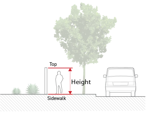
Where no sidewalk exists within five feet of a wall or fence, height is measured vertically from the topmost point of the wall or fence to the finished grade at the base of the wall or fence on the side that faces outward from the lot.
To measure retaining walls see Sec. 4C.9.2. (Retaining Walls).
Fence/wall height maximums listed as "Prohibited" allow no fence or wall within the frontage yard.
Hedge Height
Hedge height is measured according to Sec. 4C.6.4.D.11. (Height at Maturity).
Hedge height maximums listed as "Prohibited" allow no hedge within the frontage yard.
Opacity
To measure opacity, see Sec. 14.2.13. (Opacity (%)).
Public Access Easement
For a lot with a public access easement, see Sec. 14.2.17.B.7. (Frontage Yard Fence & Wall).
Exceptions
Fences and walls located in a frontage yard may integrate outdoor lighting, entry arbors, and other accessory encroaching elements that exceed the maximum fence/wall height specified by the applicable frontage yard fence & wall type, provided all of the following are met:
The cumulative length of fence or wall that includes encroaching elements is no more than 10 percent of the total fence length located in the frontage yard,
No individual encroaching element may be wider than six feet, measured along the length of the fence or wall,
One encroaching element for each 40 feet of fence length may exceed the maximum fence and wall height by up to 40 inches. All other encroaching elements shall only exceed the maximum fence and wall height up to 18 inches.
Where a required frontage screen or transition screen includes a fence or wall minimum height requirement that exceeds the maximum height allowed in Paragraph 2. (Frontage Yard Fence & Wall Types) of Subsection C. (Standards) above, the maximum fence and wall height allowed shall instead be the fence and wall height specified by the required applicable screening standards.
Relief
A deviation up to 15 percent from any allowed frontage yard fence & wall type dimensional standard may be granted in accordance with Sec. 13B.5.2. (Adjustment).
A deviation from any allowed frontage yard fence & wall type standard may be granted as a variance in accordance with Sec. 13B.5.3. (Variance).


Div. 3C.4. Transparency
Sec. 3C.4.1. Transparent Area
Transparent area is defined as the amount of transparent area on a building facade.
Intent
The intent of the standards of this Section (Transparent Area) is to provide visual interest along the public realm by encouraging visual connections between the public realm and the interior of a building.
Applicability
Transparent area standards apply to the following project activities when "transparent area" is required by the applied Frontage District (Part 3B.): new construction, a major remodel, and an exterior modification. When the transparent area standards apply, the standards apply pursuant to Sec. 3A.2.2.B.3. (Frontage Applicable Facades) and Sec. 3A.2.2.B.4. (Frontage Applicable Building Depth).
Standards
Each applicable facade shall provide at least the minimum transparency specified by the applied Frontage District (Part 3B.).
Window and door openings meeting the following requirements count toward transparent area:
No walls, shelving, facade screens, or other interior or exterior visual obstructions shall be located within five feet of any ground story transparent area with the exception of visual obstructions allowed in subparagraph d below.
Exterior visual obstructions shall not be located within five feet of any upper story transparent area with the exception of visual obstructions allowed in subparagraph d below.
Visual obstructions may be located five feet or greater from a facade area counting toward transparent area.

The following visual obstructions may be located less than five feet from facade area counting toward transparent area:
Windows obscured by interior security gates and window displays may count toward transparent area, provided no more than 25 percent of the transparent area of any individual window is visually obstructed for any individual window counting toward transparent area. For measuring visual obstruction, see Sec. 14.2.13. (Opacity (%)).
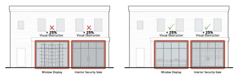
Windows obscured by fixed exterior facade screens may count toward transparent area, provided no more than 25 percent of the total transparent area is visually obstructed for any individual window opening counting toward transparent area. Percentage of visual obstruction is measured as opacity.
Transparent area covered by window signs may count toward transparent area provided the window signs are permitted by the applied Development Standards District (Part 4B.).
Areas of transparency may be made temporarily opaque by operable window treatments, such as curtains or blinds.
Distance from transparent area is measured perpendicular to the exterior face of the transparent area.
To be considered transparent, window and door glazing shall meet the following requirements:
Transparent Area Standards
Visible Light
TransmittanceExternal
ReflectanceGround story
More than 60%
Less than 20%
Upper stories
More than 30%
Less than 40%
Muntins, mullions, window sashes, window frames, and door frames, no more than three inches wide may be considered transparent area when contained within a window opening or door opening occupied by a window or glazed door assembly where all included glazing meets the transparent area requirements above.

Measurement
Ground Story
Ground story transparency is a percentage, calculated as the sum of all ground story facade area meeting the standards for transparent area divided by the total ground story facade area.
In calculating ground story transparency, ground story facade area is measured in the following ways:
Ground story facade area is measured as the above-grade facade area between zero and 12 feet above the top of the finished floor of the ground story.

If the ground story height is less than 12 feet, the ground story facade area is measured as the total above-grade portion of a facade between the top of the finished floor of the ground story and the top of the finished floor above. When there is no story above, ground story height is measured to the top of the uppermost surface of the ceiling structure above.
No portion of a ground story located below finished grade is included in ground story facade area.

Upper Stories
The facade area along each upper story shall meet the required transparency standard. .
Upper story transparency is a percentage, calculated as the sum of all upper story facade area meeting the standards for transparent area divided by the total upper story facade area for each story.
In calculating upper story transparency, the upper story facade area is measured as the portion of a facade area between the top of the finished floor for that story to the top of the finished floor above, regardless of story height. When there is no story above, it is measured to the top of the uppermost surface of the ceiling structure above.

Exceptions
Transparent area standards do not apply to portions of building facades that enclose a parking structure except where parking structures are required to be wrapped by the applied Development Standards District (Part 4B.).
Relief
Up to a 10 percent reduction from the total required transparent area may be granted in accordance with Sec. 13B.5.2. (Adjustment).
A deviation from required transparent area standards may be granted as a variance in accordance with Sec. 13B.5.3. (Variance).


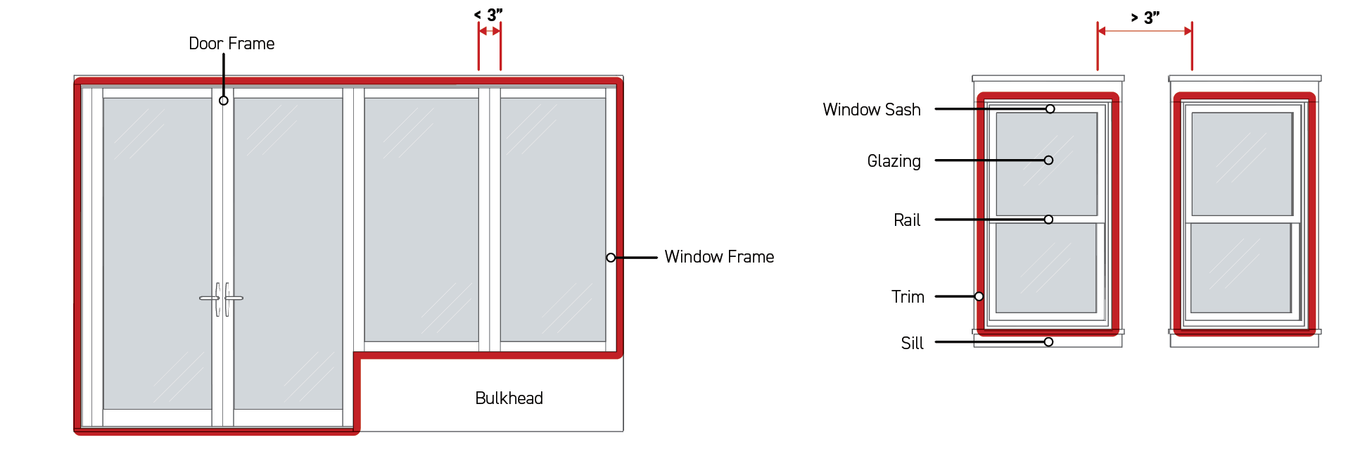


Sec. 3C.4.2. Active Wall Spacing
Active wall spacing is defined as the horizontal distance between widths of ground story facade and foundation wall with window or door openings.
Intent
The intent of the standards of this Section (Active Wall Spacing) is to provide visual interest and activation along the public realm by limiting areas without visual or physical connections between the public realm and the interior of a building.
Applicability
Active wall spacing standards apply to new construction, a major remodel, or an exterior modification.
Active wall spacing standards apply to the following facades:
All portions of ground story frontage applicable facades pursuant to Sec. 3A.2.2.B.3. (Frontage Applicable Facades) located between three feet and eight feet from the ground floor elevation measured vertically.

All portions of foundation walls on frontage applicable facades pursuant to Sec. 3A.2.2.B.3. (Frontage Applicable Facades) that are exposed four feet in height or greater above sidewalk grade. If foundation walls are set back more than 10 feet from a sidewalk, exposed height is measured from the lowest elevation of finished grade within five feet, measured from and perpendicular to the foundation wall.

Standards
Active Wall Spacing on Ground Story Facade
Window and door openings meeting Sec. 3C.4.1. (Transparent Area) on ground story facades shall be separated by a distance no greater than the maximum active wall spacing. For exceptions to this standard, see Subsection E. (Exceptions) below.
Active Wall Spacing on Foundation Wall
Applicable portions of foundation walls shall be no wider than the maximum active wall spacing specified by the applied Frontage District (Part 3B). For exceptions to this standard, see Subsection E. (Exceptions) below.
Measurement
Active Wall Spacing on Ground Story Facade
Active wall spacing is measured horizontally and parallel to the frontage lot line from edge of transparent area to edge of transparent area, and edge of transparent area to edge of ground story facade.

Active Wall Spacing on Foundation Wall
Active wall spacing is measured horizontally for any individual width of applicable foundation wall that does not include transparent area.

Exceptions
Inapplicable Facades
Active wall spacing standards do not apply to upper story facades.
Active wall spacing standards do not apply to portions of building facades enclosing a parking structure except where parking structures are required to be wrapped or fenestrated by the applied Development Standards District (Part 4B).
Inactive Wall Treatment Alternatives
Ground story facades that exceed the maximum allowed active wall spacing may apply one or more ground story inactive wall treatment alternatives to the applicable facade area between door or window openings and increase the active wall spacing by 50 percent per Paragraph 3. (Ground Story Inactive Wall Treatment Alternatives) below.
Facades designed with foundation walls that exceed the maximum allowed active wall spacing may apply one or more foundation inactive wall treatment alternatives to the facade area between active foundation walls and double the allowed active wall spacing per Paragraph 4. (Foundation Inactive Wall Treatment Alternatives) below.
Plants provided to meet the requirements of Paragraph 3. (Ground Story Inactive Wall Treatment Alternatives) and Paragraph 4. (Foundation Inactive Wall Treatment Alternatives) below shall also comply with Div. 4C.6. (Plants).
Ground Story Inactive Wall Treatment Alternatives
Permanent design improvements located between segments of ground story active wall and the public realm, designed to improve visual interest and the pedestrian experience.
a.Small Trees
Small trees planted between a ground story facade with no window or door openings and the public realm.

Dimensional Standards
For measurement see Sec. 3C.4.2.E.5.
A
Treatment width (min portion of inactive wall)
100%
Tree type
Small species
B
Planting frequency (min avg.)
5 per 100'
C
Planting area depth (min)
7'
See Div. 4C.6. (Plants) for additional standards.
b.Large Trees
Large trees planted between a ground story facade with no window or door openings and the public realm.

Dimensional Standards
For measurement see Sec. 3C.4.2.E.5.
A
Treatment width (min portion of inactive wall)
100%
Tree type
Large species
B
Planting frequency (min avg.)
3 per 100'
C
Planting area depth (min)
15'
See Div. 4C.6. (Plants) for additional standards.
c.Living Wall
A permanently fixed assembly located between a ground story facade with no window or door openings and the public realm that supports plants, their growing medium, and irrigation.
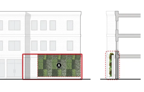
Dimensional Standards
For measurement see Sec. 3C.4.2.E.5.
A
Treatment area (min % of ground story facade with inactive walls)
75%
Planting area depth (min)
n/a
See Div. 4C.6. (Plants) for additional standards.
d.Colonnade
A sequence of columns located between a ground story facade with no window or door openings and the public realm, providing an exterior occupiable space along the inactive wall.

Dimensional Standards
For measurement see Sec. 3C.4.2.E.5.
A
Treatment width (min portion of inactive wall)
100%
B
Column frequency (min avg.)
1 per 20'
C
Clear depth (min)
6'
Enclosure (max)
60%
Foundation Inactive Wall Treatment Alternatives
Permanent design improvements located between exposed foundation walls and the public realm, designed to improve visual interest and the pedestrian experience.
a.Foundation Planting
Screening plants located between a foundation wall with no window or door openings and the public realm.

Dimensional Standards
For measurement see Sec. 3C.4.2.E.5.
A
Treatment width (min portion of inactive wall)
75%
Plant type
Screening Plant
Planting frequency (min avg.)
3 per 10'
Planting area depth (min)
3'
See Div. 4C.6. (Plants) for additional standards.
b.Planter
Permanent structure containing plants and their growing medium located between a foundation wall with no window or door openings and the public realm.

Dimensional Standards
For measurement see Sec. 3C.4.2.E.5.
A
Treatment width (min)
75%
Plant coverage (min)
75%
Planting area depth (min)
2.5'
B
Height above sidewalk (max)
4'
C
Foundation wall reveal (max)
2'
See Div. 4C.6. (Plants) for additional standards.
c.Green wall
A structure permanently attached to a foundation wall with no window or door openings that supports climbing plants.

Dimensional Standards
For measurement see Sec. 3C.4.2.E.5.
A
Treatment area (min)
75%
Planting area depth (min)
1.5'
See Div. 4C.6. (Plants) for additional standards.
d.Pedestrian Access
Stairs or ramps providing pedestrian access to a street-facing entrance located between a foundation wall with no window or door openings and the public realm.

Dimensional Standards
For measurement see Sec. 3C.4.2.E.5.
A
Treatment width (min)
75%
B
Height above sidewalk (max)
4'
Additional access standards
See Div. 4C.1.
See Div. 4C.1. (Pedestrian Access) for additional standards.
e.Seating
A permanent structure designed and intended for public seating located between a foundation wall with no window or door openings and the public realm.
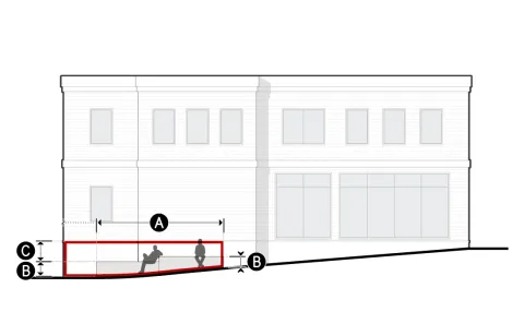
Dimensional Standards
For measurement see Sec. 3C.4.2.E.5.
A
Treatment width (min)
75%
B
Height above sidewalk (min/max)
1.5'/3'
C
Foundation wall reveal (max)
3'
Seat depth (min)
2'
Inactive Wall Treatment Measurement
Treatment Width
Minimum treatment width percentage is calculated as the cumulative width of the provided inactive wall treatments divided by the total width of the provided active wall spacing.
Treatment Area
Minimum treatment area percentage is calculated as the cumulative area of the provided inactive wall treatments divided by the total applicable facade area within the provided active wall spacing.
Tree type
Tree type is measured as small or large species according to Sec. 4C.6.4.C.3.a.ii. (Tree Types).
Plant type
Plant type is measured as screening plants, groundcover, and turf plants, hedges, living walls, or climbing plants according to Sec. 4C.6.4. (Plant Design & Installation).
Plant Coverage
Minimum plant coverage is measured according to Sec. 4C.6.4.D.2. (Plant Coverage).
Planting Frequency
Planting frequency is a ratio of the minimum number of plants required over a specified width of active wall spacing. A minimum of one plant of the required plant type shall be provided regardless of the width of inactive wall treatment.
Column Frequency
Minimum column frequency is a ratio of the minimum number of columns required over a specified width of treated inactive wall treatment. A minimum of two columns shall be provided regardless of the inactive wall treatment width.
Planting Area Depth
Minimum planting area depth is measured as the horizontal dimension of growing medium at the narrowest point, measured perpendicular to the applicable street lot line. The planting area shall be open to the sky for at least the required planting area depth.
Clear Depth
Minimum clear depth is measured as the horizontal dimension of the occupiable portion of an architectural element at the narrowest point.
Height Above Sidewalk
Height above sidewalk is measured vertically from adjacent sidewalk grade to the topmost point of the inactive wall treatment.
For foundation walls located more than 10 feet from a sidewalk, maximum height above sidewalk is measured from the lowest elevation of finished grade within five feet, measured from and perpendicular to the foundation wall, to the topmost point of the inactive wall treatment.
Foundation Wall Reveal
Foundation wall reveal is measured vertically from the top of an inactive wall treatment to the ground floor elevation along the entire treated portion of an inactive foundation wall.
Seat Depth
Minimum seat depth is measured as the narrowest horizontal dimension of the area designed for public seating.
Enclosure
Maximum enclosure is measured according to Sec. 14.2.4. (Enclosure).
Relief
Deviation from inactive wall treatment standards may be granted in accordance with Sec. 13B.5.1. (Alternative Compliance).
An increase in allowed active wall spacing up to 20 percent may be granted in accordance with Sec. 13B.5.2. (Adjustment).
An increase in allowed active wall spacing and inactive wall treatment standards may be granted as a variance in accordance with Sec. 13B.5.3. (Variance).


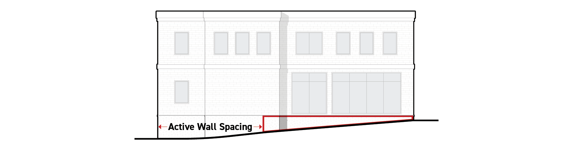
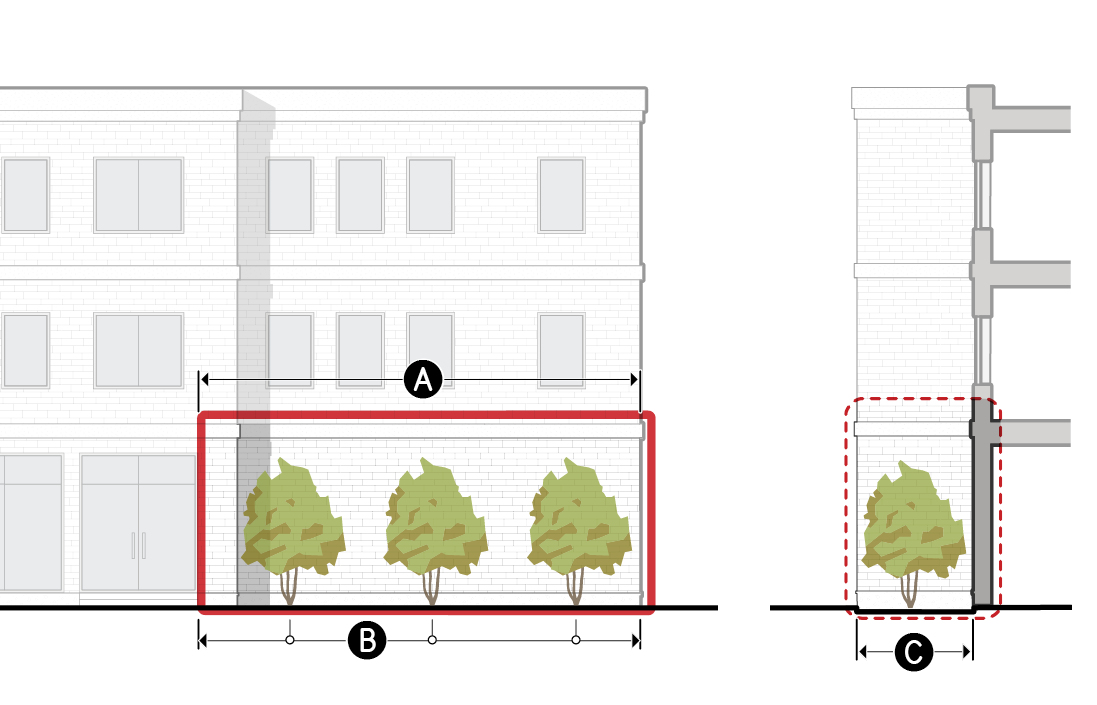


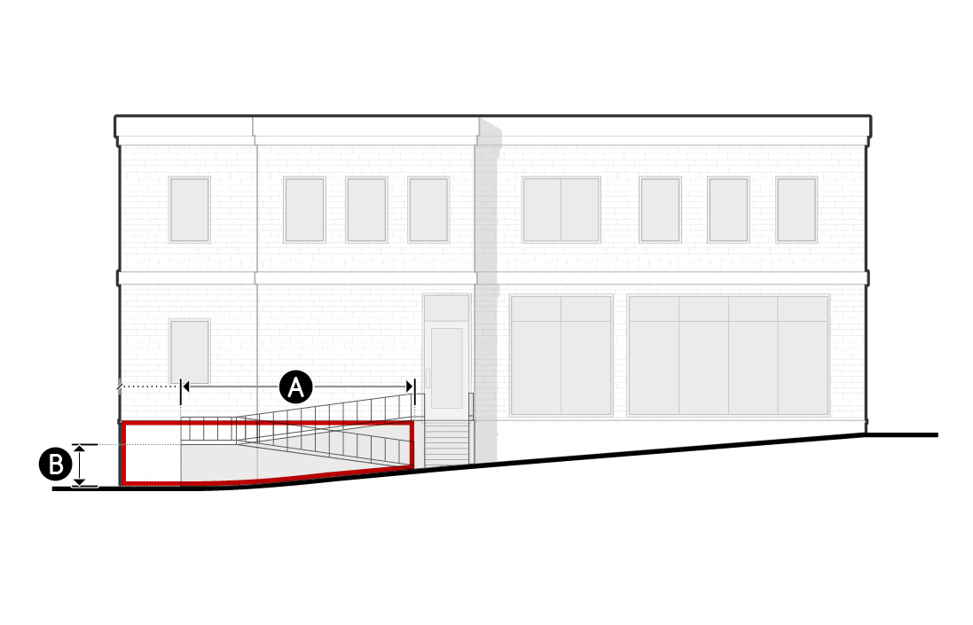

Div. 3C.5. Entrances
Sec. 3C.5.1. Street-Facing Entrance
Street-facing entrance is defined as a door providing access from the public realm to the interior of a building.
Intent
The intent of the standards of this Section (Street-Facing Entrance) is to provide visual interest along the public realm, orient buildings to the public realm, and promote greater use and activation of the public sidewalk by limiting the width of frontage without physical connections between the public realm and the interior of a building.
Applicability
Street-facing entrance standards apply to new construction, a major remodel, or an exterior modification. When the street-facing entrance standards apply, the standards apply to those portions of buildings and structures where frontage standards apply pursuant to Sec. 3A.2.2.B. (Applicable Components of Lots, Buildings, & Structures).
Standards
General
Where a street-facing entrance is required by the applied Frontage District, street-facing entrances shall be provided at a rate based on the maximum entrance spacing specified in the applied Frontage District. A minimum of one street-facing entrance shall always be provided.
To qualify as a street-facing entrance, building entrances shall meet the following standards:
Be located on the ground story facade.
Provide both ingress and egress pedestrian access to the ground story of the building.
Remain operable at all times. Access may be controlled and limited to residents or tenants.
Provide no access directly to motor vehicle use areas, utility areas or fire stairs.
The exterior door surface shall be angled between zero to 60 degrees, measured parallel to the frontage lot line or the door shall have direct access from an entry feature allowed by the applied Frontage District (Part 3B.) having a pedestrian access point which faces the frontage lot line.
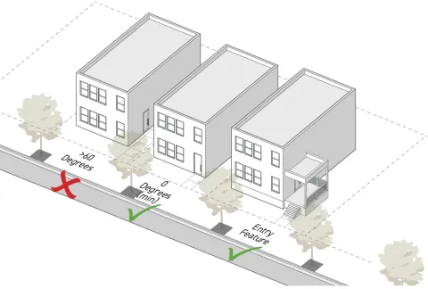
On a corner lot or a lot with a Dual Frontage District (Div. 3B.8.) applied, having intersecting frontage lot lines, an entrance facing both intersecting frontage lot lines and angled between 30 to 60 degrees, measured parallel to each of those frontage lot lines, may be used to meet the requirement for a street-facing entrance along both frontages.

Non-required entrances are allowed in addition to required entrances.
Entrance Spacing
The distance between street-facing entrances meeting the standards of Sec. 3C.5.1.C. (Standards).
Measurement
The minimum number of street-facing entrances required for each frontage applicable facade is the frontage-applicable facade width divided by the maximum entry spacing requirement.
Maximum entrance spacing is the greatest horizontal distance from edge of door to edge of door, and edge of door to edge of building, measured parallel to the frontage lot line.
Standards
Street-facing entrances shall not be separated by a distance greater than the maximum allowed entrance spacing.
The maximum entrance spacing requirements shall be met for each building individually, but are not applicable to adjacent or abutting buildings.
When the applied Frontage District (Part 3B.) specifies that a street-facing entrance is 'not required' but does specify a maximum entrance spacing, a street-facing entrance shall only be required if the building width along the indicated frontage lot line is greater than the specified entrance spacing. Street-facing entrances shall then be required in accordance with the maximum entrance spacing requirement specified.
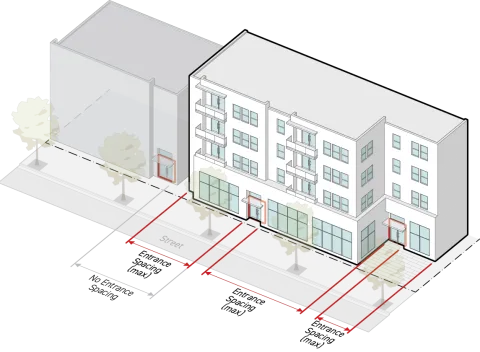
Measurement
Street-facing entrance is measured as "provided" or "not provided" based on the presence of entrances meeting Sec. 3C.5.1.C. (Standards).
Relief
Deviation from street-facing entrance standards may be granted in accordance with Sec. 13B.5.1. (Alternative Compliance).
An increase in entrance spacing up to 20 percent may be granted in accordance with Sec. 13B.5.2. (Adjustment).
Deviation from street-facing entrance and entrance spacing standards may be granted as a variance in accordance with Sec. 13B.5.3. (Variance).


Sec. 3C.5.2. Entry Feature
Entry features are improved design standards applied to each entrance along the public realm.
Intent
The intent of the standards of this Section (Entry Feature) is to provide architectural embellishment of entrances that promote inconspicuous wayfinding in the public realm, provide greater shelter and comfort to users, promote visual interest along the public realm, and highlight the connection between the public and private realm to improve walkability.
Applicability
Entry feature standards apply to all required street-facing entrances where entry features are required by the applied Frontage District (Part 3B.).
Standards
General
Each required street-facing entrance shall include an entry feature that meet the standards for one of the allowed entry feature options specified by the applied Frontage District (Part 3B.).
Required entry features shall abut and provide direct access to a street-facing entrance.
Required entry features shall provide direct access from the public realm associated with the frontage lot line.
For building setback encroachment regulations, see Sec. 2C.2.2.E. (Exceptions).
For encroachments into the public right-of-way, see Chapter IX. (Building Regulations), Sec. 91.32 (Encroachments into the Public Right-of-Way) of this Code.
In complying with entry feature standards, outdoor spaces such as landings and yards required by an entry feature count as occupiable space.
Entry Feature Options
Packages of design standards applied to each entrance along the public realm.
a.Porch
A wide, raised platform, projecting in front of a street-facing entrance, that is entirely covered but not enclosed.

Dimensional Standards
For measurement see Sec. 3C.5.2.D.
A
Clear depth (min)
4.5'
B
Clear width (min)
12'
Clear height (min)
7.5'
Covered area (min)
100%
C
Finished floor elevation (min/max)
2'/5'
Enclosure (max)
50%
b.Raised Entry
A raised platform accessed from an exterior staircase, providing covered access to a street-facing entrance.
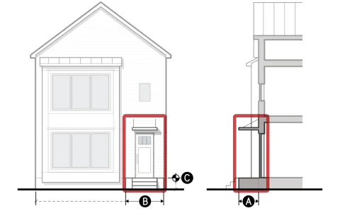
Dimensional Standards
For measurement see Sec. 3C.5.2.D.
A
Clear depth (min)
3'
B
Clear width (min)
4'
Clear height (min)
7.5'
Covered entrance
Required
C
Finished floor elevation (min/max)
2'/5'
Enclosure (max)
50%
c.Forecourt
A yard screened with a short wall, fence or hedge that provides significant privacy for tenants located on the ground story, near sidewalk grade.

Dimensional Standards
For measurement see Sec. 3C.5.2.D.
A
Clear depth (min)
8'
B
Clear width (min)
10'
Clear height (min)
Open to sky
Covered entrance
Required
C
Finished floor elevation (min/max)
-2'/2'
Fence or wall height (min/max)
2.5'/4'
d.River Yard
A yard located between a building and a river trail with direct pedestrian access from inside the building to the river trail.

Dimensional Standards
For measurement see Sec. 3C.5.2.D.
A
Clear depth (min)
15'
B
Clear width (min)
15'
Clear height (min)
Open to sky
C
Finished floor elevation (min/max)
-2'/2'
Fence or wall height (max)
6'
e.Recessed Entry
A space set behind the building face plane providing sheltered access to a street-facing entrance.

Dimensional Standards
For measurement see Sec. 3C.5.2.D.
A
Clear depth (min)
3'/15'
B
Clear width (min)
5'
Clear height (min)
7.5'
Covered entrance
Required
C
Finished floor elevation (min/max)
-2'/2'
Enclosure (max)
75%
f.Covered Entry
A space that provides sheltered access to an at-grade street-facing entrance with an overhead projecting structure.

Dimensional Standards
For measurement see Sec. 3C.5.2.D.
Clear height (min)
7.5'
A
Covered entrance
Required
B
Finished floor elevation (min/max)
-2'/2'
Enclosure (max)
50%
For encroachments into the public right-of-way, see Chapter IX. (Building Regulations), Sec. 91.32. (Encroachments into the Public Right-of-Way) of this Code.
g.Storefront Bay
A facade area with a high level of contiguous transparency accentuating an at-grade street-facing entrance.

Dimensional Standards
For measurement see Sec. 3C.5.2.D.
A
Transparent area height (min)
9'
B
Transparent area width (min)
8'
Covered entrance
Required
C
Finished floor elevation (min/max)
-2'/2'
D
Transparency (min)
90%
Fence or wall height (max)
0'
h.Market Stall
A facade area equipped with an overhead door or operable facade that is open to the public realm during hours of operation.

Dimensional Standards
For measurement see Sec. 3C.5.2.D.
Clear depth (min)
10'
A
Clear height (min)
9'
B
Clear width (min)
6'
C
Finished floor elevation (min/max)
-2'/5'
Fence or wall height (max)
0'
A market stall does not count toward transparency unless it meets the standards for transparent area when shut.
Measurement
General
Entry feature is measured as "provided" or "not provided" for each required street-facing entrance based on whether the design of a street-facing entrance meets the standards of an allowed entry feature specified by the applied Frontage District (Part 3B.).
In complying with entry feature standards, outdoor spaces such as landings and yards required by an entry feature count as occupiable space.
Clear Depth
Clear depth is measured as the shallowest horizontal dimension of the occupiable space immediately abutting or surrounding each required street-facing entrance, measured perpendicular to the applicable building facade to the interior of the occupiable space.
Clear Width
Clear width is measured as the narrowest horizontal dimension of the occupiable space immediately abutting or surrounding each required street-facing entrance, measured parallel to the applicable street lot line.
Clear Height
Clear height is measured vertically at the shortest point between the finished floor elevation or the finished grade of the occupiable space immediately abutting or surrounding each required street-facing entrance to the bottom of the surface of any solid overhead structure creating covered space within the occupiable space.
Where a minimum clear height is specified as 'open to sky', the occupiable space immediately abutting each required street-facing entrance shall be uncovered.
Covered Entrance
When required as part of an entry feature, a canopy, roof or other sheltering structure, the covered entrance shall cover the occupiable exterior area immediately abutting the associated street-facing entrance.
The minimum depth of the covered area shall be the clear height of the covered area divided by three.
The minimum width of the covered area shall be the clear height of the covered area divided by two.

Covered Area
Covered area is measured as the occupiable space of an entry feature that is covered by a canopy, roof or other sheltering structure, divided by the total occupiable entry feature area.
Finished Floor Elevation
Finished floor elevation is measured from the average sidewalk grade along the adjacent sidewalk to the top of the finished floor surface or ground surface of the entry feature. Where no sidewalk exists within 10 feet of the entry feature, finished floor elevation is measured perpendicular from the average finished grade within five feet of the entry feature, to the entry feature area.
Transparency
Transparency is the percentage of area meeting the transparent area standards of Sec. 3C.4.1.C. (Standards) provided for each street-facing entrance, divided by the required transparent area.
Required transparent area is calculated by multiplying the specified transparent area height by transparent area width. For the measurement of ground story transparency, see Sec. 3C.4.1.D.1. (Ground Story).
Transparent Area Height
Transparent area height is measured vertically from the top of the finished floor of the ground story to the shortest height of the transparent area provided.
Transparent Area Width
Transparent area width is measured horizontally from the outer edges of the transparent area provided along the narrowest width.
Enclosure
For the measurement of enclosure, see Sec. 14.2.4. (Enclosure).
Fence or Wall Height
Fence or wall height is measured according to Sec. 3C.3.2.D.2. (Fence & Wall Height).
Relief
A deviation from entry feature dimensional standard up to 15 percent may be granted in accordance with Sec. 13B.5.2. (Adjustment).
Deviation from any entry feature standard may be granted as a variance in accordance with Sec. 13B.5.3. (Variance).


Div. 3C.6. Ground Story
Sec. 3C.6.1. Ground Story Height
Ground story height is defined as the floor-to-floor height of the story of a building having its finished floor elevation nearest to the finished grade.
Intent
The intent of the standards of this Section (Ground Story Height) is to promote active uses that are directly connected to the public realm, and ensure high-quality ground story spaces that are adaptable and appropriate to their context.
Applicability
Ground story height standards apply to new construction. When the ground story height standards apply, the standards apply to all portions of the ground story, within the first 15 feet of a facade of a new building or structure, pursuant to Sec. 3A.2.2.B.3. (Frontage Applicable Facades).
Standards
All occupiable space located in applicable portions of the ground story shall have floor-to-floor height of no less than the ground story height minimum.
Measurement
Ground story height is measured vertically from the top of the finished ground story to the top of the finished floor above.
Where no story exists above, ground story height is the shortest vertical distance from the top of the ground floor elevation to the top of the ceiling or roof structure above.
For determining the ground story, see Sec. 14.2.10.A. (Ground Story).
Relief
A reduction in required ground story height up to one foot may be granted in accordance with Sec. 13B.5.2. (Adjustment).
Deviation from ground story height standards may be granted as a variance in accordance with Sec. 13B.5.3. (Variance).
Sec. 3C.6.2. Ground Floor Elevation
Ground floor elevation is defined as the finished floor height associated with the story of a building having its finished floor elevation nearest to the finished grade.
Intent
The intent of the standards of this Section (Ground Floor Elevation) is to promote high-quality ground story spaces with direct connection and visual interplay with the public realm.
Applicability
Ground floor elevation standards apply to new construction subject to the following:
For structures located less than 20 feet from the frontage lot line, all portions of the ground story located within the first 15 feet of a frontage applicable facade pursuant to Sec. 3A.2.2.B.3. (Frontage Applicable Facades), measured inward and perpendicular to the frontage lot line, shall comply with ground floor elevation standards.

Standards
All occupiable space located in applicable portions of the ground story shall have a ground floor elevation no higher than the maximum ground floor elevation specified by the applied Frontage District (Part 3B.).
All occupiable space located in applicable portions of the ground story shall have a ground floor elevation no lower than the minimum ground floor elevation specified by the applied Frontage District (Part 3B.).
Measurement
Where a building is located greater than 10 feet from a public sidewalk, ground story height is measured vertically from the average finished grade within five feet of the frontage lot line facing building perimeter to the finished floor elevation of the ground story.
Where a building is located 10 feet or less from a public sidewalk, ground floor elevation is measured vertically from the average sidewalk grade to the finished floor elevation of the ground story. Average sidewalk grade is measured as the average of the highest and lowest sidewalk elevation for the portion of the sidewalk located in front of the building.

Ground floor elevation shall be measured independently for different modules of the building width. The ground floor elevation for each module shall be measured from either average sidewalk grade for the portion of the sidewalk in front of the module or from average finished grade within five feet of the frontage lot line facing building perimeter based on the distance of the building module from a public sidewalk according to Paragraph 1. and Paragraph 2. above.
For sloped lots, average elevation along the sidewalk shall be measured individually for each module and calculated as the average of the highest and lowest sidewalk elevation for the portion of the sidewalk located in front of the building module.

Exceptions
Ground floor elevation standards do not apply to structures located 20 feet or greater from the frontage lot line.
Relief
A deviation in minimum or maximum ground floor elevation up to 10 percent may be granted in accordance with Sec. 13B.5.2. (Adjustment).
Deviation from ground floor elevation standards may be granted as a variance in accordance with Sec. 13B.5.3. (Variance).


Part 3D. Character Frontage Rules
Div. 3D.1. Build-To
Div. 3D.2. Parking
See Div. 3C.2. (Parking).
Div. 3D.3. Landscaping
Div. 3D.4. Ground Floor Elevation
Div. 3D.5. Story Height
Sec. 3D.5.1. Ground Story Height
For the intent, applicability, standards, measurement, and relief of ground story height see Sec. 3C.6.1. (Ground Story Height).
Sec. 3D.5.2. Upper Story Height
Upper story height is defined as the floor-to-floor height of any story of a building located above the ground story.
Intent
The intent of the standards of this Section (Upper Story Height) is to ensure upper story spaces and their facades are scaled and proportioned to contribute to the established architectural character of surrounding neighborhoods or districts.
Applicability
Upper story height standards apply to new construction of multi-story buildings or structures. When upper story height standards apply, the standards apply to each story located above the ground story and all build-to applicable stories specified by the applied Frontage District (Part 3B.).
Standards
All occupiable space located in applicable portions of upper stories shall have a floor-to-floor height of no less than the upper story height minimum.
Measurement
Upper story height is measured vertically from the top of the finished floor to the top of the finished floor above.
Where no story exists above an upper story, upper story height is the shortest vertical distance from the top of the finished floor to the top of the ceiling or roof structure above.
Exceptions
Portions of upper stories located beyond the first 15 feet of a frontage applicable facade, measured inward and perpendicular to the facade are not required to meet upper story height standards.
Relief
A reduction in required upper story height of up to one foot may be granted in accordance with Sec. 13B.5.2. (Adjustment).
Deviations from upper story height standards may be granted as a variance in accordance with Sec. 13B.5.3. (Variance).
Div. 3D.6. Articulation
Sec. 3D.6.1. Base, Middle & Top Articulation
The base, middle & top articulation requirement is composed of three separate and coordinated articulating elements designed to visually break a building facade up into three separately legible layers.
Intent
The intent of the standards of this Section (Base, Middle & Top Articulation) is to visually break a building facade up into three separately legible building layers.
Applicability
Base, middle & top articulation standards apply to new construction or any exterior modification when the applied Character Frontage District (Div. 3B.9.) requires base, middle & top articulation on facades pursuant to Sec. 3A.2.2.B.3. (Frontage Applicable Facades).
Standards
General
One articulating element option shall be provided for each building layer in accordance with the building layer standards below.
Building Layers

Base
The base building layer shall include at least one and no more than three contiguous stories starting with the ground story and continuing upward.
At least one of the following articulating elements shall be applied along the top of the base layer, creating a transition between the base and middle layers:
The articulating element shall extend for the full width of the building and be located no higher than the top of the uppermost story included in the layer.
Middle
The middle building layer shall include at least twice as many contiguous stories than the base building layer, starting at the top of the base layer and continuing upward.
At least one of the following articulating elements shall be applied along the top of the middle layer, creating a transition between the middle and top layers:
The articulating element shall extend for the full width of the building and be located no higher than the top of the uppermost story included in the layer.
Top
The top building layer shall include at least one story and shall not include more stories than the base building layer.
All stories located in the top building layer shall be contiguous and include, at minimum, all stories between the top of the middle layer and the top of the highest of the build-to applicable stories specified by the applied Frontage District (Part 3B.).
A roofline cornice articulating element shall be applied to the top building layer when the top building layer is the topmost story of the building or the topmost story before a street step-back. See Sec. 3D.6.5.C.4. (Roofline Cornice).
The roofline cornice shall extend for the full width of the building and be located along the top of the topmost story included in the building layer.
When the top building layer does not include the topmost story of the building or the topmost story before a street step-back, at least one of the following articulating elements shall be applied along the top of the top layer, creating a transition between the top building layer and any story above:
The articulating element shall extend for the full width of the building and be located along the top of the topmost story included in the building layer.
Measurement
For measurement of stories see Sec. 2C.4.3. (Height in Stories).
Exceptions
Where the applied Form District (Part 2B.) requires a street step-back depth of 10 feet or greater, the top building layer may terminate at the topmost story below the street step-back. No articulating element is required above the top building layer.
When a building is less than five stories, the standards of this Section (Base, Middle & Top Articulation) do not apply, and the standards of Sec. 3D.6.2. (Base-Top Articulation) apply.
Relief
Base, middle & top articulation standards may be met through alternative compliance in accordance with Sec. 13B.5.1. (Alternative Compliance).
A deviation from number of stories in building layers of one story may be granted in accordance with Sec. 13B.5.2. (Adjustment).
Deviation from any base, middle & top articulation standard may be granted as a variance in accordance with Sec. 13B.5.3. (Variance).

Sec. 3D.6.2. Base-Top Articulation
The base-top articulation requirement is composed of two separate and coordinated articulating elements designed to visually break a building facade up into two separately legible layers.
Intent
The intent of the standards of this Section (Base-Top Articulation) is to visually break a building facade up into two separately legible building layers.
Applicability
Base-top articulation standards apply to new construction and any exterior modification of a building or structure possessing five stories or fewer when the applied Character Frontage District (Div. 3B.9.) requires base-top articulation on all facades pursuant to Sec. 3A.2.2.B.3. (Frontage Applicable Facades).
Standards
General
One articulating element option shall be provided for each building layer in accordance with the building layer standards below. See Sec. 3D.6.5. (Articulating Elements).
Building Layers
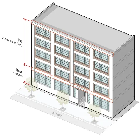
Base
The base building layer shall include between one and three contiguous stories starting with the ground story and continuing upward.
At least one of the following articulating elements shall be applied along the top of the base layer, creating a transition between the base and top layers:
The articulating element shall extend for the full width of the facade and be located no higher than the top of the uppermost story included in the layer.
Top
The top building layer shall include at least twice as many stories as the base building layer, and include all remaining above-grade stories not included in the base building layer or include all remaining above-grade stories up to a street step-back of no less than 15 feet in depth. If the building is less than three stories, or less than three stories without a street step-back of at least 15 feet in depth, the top layer may be composed of one story regardless of the height of the base building layer.
A roofline cornice articulating element shall be applied to the top building layer that is the topmost story of the building or the topmost story before a street step-back. See Sec. 3D.6.5.C.4. (Roofline Cornice).
The roofline cornice shall extend for the full width of the facade and be located along the top of the topmost story included in the building layer.
When the top building layer does not include the topmost story of the building or the topmost story before a street step-back, at least one of the following articulating elements shall be applied along the top of the top layer, creating a transition between the top building layer and any story above:
The articulating element shall extend for the full width of the building and be located along the top of the topmost story included in the building layer.
Measurement
For measurement of stories see Sec. 2C.4.3. (Height in Stories).
Exceptions
Where the applied Form District (Part 2B.) requires a street step-back depth of 10 feet or greater, the top building layer may terminate at the topmost story below the street step-back. No articulating element is required above the top building layer.
Relief
Base-top articulation standards may be met through alternative compliance in accordance with Sec. 13B.5.1. (Alternative Compliance).
A deviation from number of stories in building layers of one story may be granted in accordance with Sec. 13B.5.2. (Adjustment).
Deviation from any base-top articulation standard may be granted as a variance in accordance with Sec. 13B.5.3. (Variance).

Sec. 3D.6.3. Horizontal Band Articulation
Horizontal band articulation is a continuous band of material running horizontally across a facade.
Intent
The intent of the standards of this Section (Horizontal Band Articulation) is to separate and align windows on a building facade in a way that contributes to the established architectural character of surrounding neighborhoods or districts.
Applicability
Horizontal band articulation standards apply to new construction or an exterior modification when the applied Character Frontage District (Div. 3B.9.) requires horizontal band articulations on facades pursuant to Sec. 3A.2.2.B.3. (Frontage Applicable Facades).
Standards
Horizontal band articulation shall meet the following standards:
Be no less than eight inches in height,
Extend for the full width of the facade, interrupted only by required articulating elements or architectural features. Architectural features that interrupt either required vertical band articulation or required horizontal band articulation shall cover cumulatively no more than 30 percent of the total facade area. A maximum of five architectural features that interrupt required vertical band articulation or horizontal band articulation are allowed on the facade area of any individual building width.
Measurement
Horizontal band articulation height is measured vertically from the lowest point to the highest point of a horizontal band articulation meeting the standards above.
The facade area covered by an architectural feature that interrupts horizontal band articulation or vertical band articulation is measured as the area of the smallest rectangle that fully circumscribes the architectural feature.
Relief
Horizontal band articulation standards may be met through alternative compliance in accordance with Sec. 13B.5.1. (Alternative Compliance).
A deviation from horizontal band articulation dimensional standards up to 15 percent may be granted in accordance with Sec. 13B.5.2. (Adjustment).
Deviation from any horizontal band articulation standard may be granted as a variance in accordance with Sec. 13B.5.3. (Variance).
Sec. 3D.6.4. Vertical Band Articulation
Vertical band articulation is a continuous band of material running vertically up a facade.
Intent
The intent of the standards of this Section (Vertical Band Articulation) is to separate and align windows on a building facade in a way that contributes to the established architectural character of surrounding neighborhoods or districts.
Applicability
Vertical band articulation standards apply to new construction or an exterior modification when the applied CharacterFrontage District (Div 3B.9.) requires vertical band articulations on facades pursuant to Sec. 3A.2.2.B.3. (Frontage Applicable Facades).
Standards
Vertical band articulation shall meet the following standards:
Be no less than eight inches in width, and
Extend uninterrupted for the full height of all build-to applicable stories, only interrupted by horizontal band articulation, required articulating elements or architectural features. Architectural features that interrupt either required vertical band articulation or required horizontal band articulation shall cover cumulatively no more than 30 percent of the total facade area. A maximum of five architectural features that interrupt required vertical band articulation or required horizontal band articulation are allowed on the facade of any individual building width.
Spacing
Vertical band articulation shall be applied across the full width of a facade separated by no more than the maximum spacing and no less than the minimum spacing specified by the applied Frontage District (Part 3B.).
Vertical band articulation shall also be located at each corner of a building facade.
Measurement
Vertical band articulation width is measured parallel to the applicable facade and horizontally from one end of a vertical band meeting the standards above to the opposite end.
Vertical band articulation spacing is measured horizontally and perpendicular to the applicable building facade from edge of vertical band to edge of vertical band.
The facade area covered by an architectural feature that interrupts horizontal band articulation or vertical band articulation is measured as the area of the smallest rectangle that fully circumscribes the architectural feature.
Relief
Vertical band articulation standards may be met through alternative compliance in accordance with Sec. 13B.5.1. (Alternative Compliance).
A deviation from vertical band articulation dimensional standards up to 15 percent may be granted in accordance with Sec. 13B.5.2. (Adjustment).
Deviation from any vertical band articulation standard may be granted as a variance in accordance with Sec. 13B.5.3. (Variance).
Sec. 3D.6.5. Articulating Elements
Articulating elements are permanent architectural details used to embellish a facade design to accentuate an articulation technique or facade composition.
Intent
The intent of the standards of this Section (Articulating Elements) is to provide visual interest to the public realm and break up a building facade with visually separate building layers in a way that contributes to the established architectural character of surrounding neighborhoods or districts.
Applicability
Articulating element standards apply to new construction or an exterior modification when the applied Character Frontage District (Div. 3B.9.) requires articulating elements on facades pursuant to Sec. 3A.2.2.B.3 (Frontage Applicable Facades).
Articulating Element Options
Material Change
Standards
The principal exterior material applied to the building layer shall be different from the principal siding treatment applied to the abutting building layers.
The principal exterior material shall be limited to those allowed by the applied Frontage District (Part 3B.).
One of the following architectural details must be provided between building layers applying the material change articulating element:
A belt course located at the transition from one principal exterior material to the next. See Paragraph 2. (Belt Course) below; or
The building layer applying a material change articulating element shall be recessed or project from the abutting building layers at least three inches.
Measurement
In measuring material change, principal exterior materials are considered different if they are entirely different materials or products having the same base material where the unit size or finish surface texture is visibly contrasting.
Recessed building layers are measured horizontally from and perpendicular to the immediately surrounding facade to the outermost point of the recessed building layer facade.
Projecting building layers are measured horizontally and perpendicular from the immediately surrounding facade to the innermost point of the projecting building layer facade.
Belt Course
A horizontal course projecting beyond the face of the surrounding building facade often shaped to mark a division in the facade wall.
Standards
A belt course shall meet the following standards:
Extend uninterrupted for the full width of the building layer.
Have a consistent profile across the width of the building.
Project a minimum of two inches from the immediately surrounding facade for some portion of the top two inches and the bottom two inches of the belt course profile,
Have a height of no less than 12 inches if located on the first story. An additional two inches in height are required for each story that the belt course is located about the first story. The greatest required minimum height is 48 inches.
Measurement
Belt course height is measured vertically from the lowest point to the highest point of the belt course profile meeting the standards in subparagraph a above.
Projection is measured perpendicularly from the immediately surrounding facade to the outermost point of a belt course meeting the standards in the subparagraph a above.
Shopfront Cornice
A continuous molded projection located above a series of display windows on the ground story facade.
Standards
A shopfront cornice shall meet the following standards:
Extend uninterrupted for the width of the building layer.
Project a minimum of four inches from the immediately surrounding facade for some portion of the top four inches and the bottom four inches of the cornice profile.
Have a height of no less than 12 inches.
Measurement
Shopfront cornice height is measured vertically from the lowest point to the highest point of the cornice profile meeting the standards in subparagraph a above.
Projection is measured perpendicularly from the immediately surrounding facade horizontally to the outermost point of a shopfront cornice meeting the standards in the subparagraph a above.
Roofline Cornice
A continuous molded projection that crowns a wall, often as part of a parapet.
Standards
A roofline cornice shall meet the following standards:
Extend uninterrupted for the full width of the building layer.
Project a minimum of four inches from the immediately surrounding facade for some portion of the top four inches of the cornice profile if located on the first, second or third stories. An additional two inches of projection are required for each story the roofline cornice is located above the third story. A minimum projection of at least 36 inches is required.
Have a height of no less than 12 inches if located on the first, second or third story. An additional two inches in height are required for each story the roofline cornice is located above the third story. A minimum height of at least 48 inches is required.
Measurement
Roofline cornice height is measured vertically from the lowest point to the highest point of the cornice profile meeting the standards above.
Projection is measured perpendicularly from the immediately surrounding facade horizontally to the outermost point of a roofline cornice meeting the standards in the subparagraph a above.
Measurement
Articulating elements are measured as "provided" or "not provided" based on whether the applicable building layer facade applies an articulating element meeting the standards above.
Relief
Articulating elements standards may be met through alternative compliance in accordance with Sec. 13B.5.1. (Alternative Compliance).
A deviation from articulating elements dimensional standards up to 10 percent may be granted in accordance with Sec. 13B.5.2. (Adjustment).
Deviation from any articulating elements standard may be granted as a variance in accordance with Sec. 13B.5.3. (Variance).
Div. 3D.7. Features
Sec. 3D.7.1. Restricted Features
Intent
The intent of the standards of this Section (Restricted Features) is to ensure facades are built in a way that contributes to the established architectural character of surrounding neighborhoods or districts by limiting the use of architectural features that are inappropriate to the historic or desired context.
Applicability
This Section (Restricted Features) applies to new construction or an exterior modification when the applied CharacterFrontage District (Part 3B.) restricts features on any facade pursuant to Sec. 3A.2.2.B.3. (Frontage Applicable Facades).
Standards
Where the applied Frontage District (Part 3B.) lists a feature as "prohibited", no applicable facade located on a build-to applicable story specified by the applied Frontage District (Part 3B.) may include any variety of listed feature.
Projecting Balcony
An unenclosed occupiable platform, located at an elevation above the ground story, that is fixed to or integrated with an exterior building facade and projects beyond the floor area of the story immediately below. Balconies include protective barriers such as railings or parapets and may be covered or uncovered.
Standards
Where the applied Frontage District (Part 3B.) lists projecting balcony as "prohibited":
No feature meeting the definition for projecting balcony above may be included on an applicable facade.
Roof terraces that meet the definition of balcony may be allowed provided they are uncovered and do not project beyond the story immediately below.
Measurement
Projecting balconies are identified as present or absent based on whether an applicable facade includes a projecting balcony as described above.
Relief
Deviation from "restricted features" standards may be met through alternative compliance in accordance with Sec. 13B.5.1. (Alternative Compliance).
Deviation from any "restricted features" standards may be granted as a variance in accordance with Sec. 13B.5.3. (Variance).
Div. 3D.8. Entrances
Sec. 3D.8.1. Street-Facing Entrance
For the intent, applicability, standards, measurement, and relief of street-facing entrance see Sec. 3C.5.1. (Street-Facing Entrance).
Sec. 3D.8.2. Entry Feature
For the intent, applicability, standards, measurement, and relief of entry features see Sec. 3C.5.2. (Entry Feature).
Sec. 3D.8.3. Focal Entry Feature
Focal entry feature are improved design standards applied to the primary entrance along the public realm.
Intent
The intent of the standards of this Section (Focal Entry Feature) is to establish a hierarchy of entrances on a building facade where a focal entry feature is the visually dominant entrance supported by secondary entrances designed with entry features.
Applicability
Focal entry feature standards apply to new construction, a major remodel, or an exterior modification, when the applied Character Frontage District (Part 3B.) requires a focal entry feature. When the focal entry feature standards apply, the focal entry feature standards apply to ground story, frontage lot line facing facades.
Standards
General
Each building width shall provide at least the minimum number of focal entry features specified by the applied Frontage District (Part 3B.).
Each required focal entry feature shall meet the standards for one of the focal entry feature options. See Sec. 3D.8.1.C.2. (Focal Entry Feature Options).
Required focal entry features shall abut and provide direct access to a street-facing entrance.
Required focal entry features shall provide direct access to the public realm associated with the frontage lot line.
For building setback encroachment regulations, see Sec. 2C.2.2.E. (Exceptions).
For encroachments into the public right-of-way, see Chapter IX. (Building Regulations), Sec. 91.32. (Encroachments into the Public Right-of-Way)of this Code.
Focal Entry Feature Options
Packages of design standards applied to the primary entrance along the public realm.
a.Archway
A curved symmetrical architectural detail spanning an opening to an exterior space, set behind the primary facade plane, providing sheltered access to a street-facing entrance.

Dimensional Standards
For measurement see Sec. 3C.5.2.D.
A
Clear depth (min)
3'
B
Clear width (min)
8'
Clear height (min)
9'
Covered entrance
Required
Covered area (min)
100%
C
Finished floor elevation (min/max)
-2'/5'
Transparency (min)
80%
Enclosure (max)
75%
b.Architrave
A decorative horizontal band above and connected to vertical bands framing an opening to an exterior space, set behind the primary facade plane, providing sheltered access to a street-facing entrance.

Dimensional Standards
For measurement see Sec. 3C.5.2.D.
A
Clear depth (min)
3'
B
Clear width (min)
8'
Clear height (min)
9'
Covered entrance
Required
Covered area (min)
100%
C
Finished floor elevation (min/max)
-2'/5'
Transparency (min)
80%
Enclosure (max)
75%
c.Canopy
A space that provides sheltered access to an at-grade street-facing entrance with an overhead projecting structure.

Dimensional Standards
For measurement see Sec. 3C.5.2.D.
A
Clear depth (min)
4'
B
Clear width (min)
8'
Clear height (min)
9'
Covered entrance
Required
Covered area (min)
n/a
C
Finished floor elevation (min/max)
-2'/2'
Transparency (min)
n/a
Enclosure (max)
50%
For encroachments into the public right-of-way, see Chapter IX. (Building Regulations), Sec. 91.32. (Encroachments into the Public Right-of-Way) of this Code.
Measurement
Relief
Deviation from focal entry feature option standards may be granted in accordance with Sec. 13B.5.1. (Alternative Compliance).
A deviation from focal entry feature dimensional standard up to 15 percent may be granted in accordance with Sec. 13B.5.2. (Adjustment).
Deviation from any entry feature standard may be granted as a variance in accordance with Sec. 13B.5.3. (Variance).


Div. 3D.9. Transparency
Sec. 3D.9.1. Ground Story
Intent
The intent of the standards of this Section (Ground Story) is to ensure projects are designed with ground story windows that contribute to the established architectural character of surrounding neighborhoods or district.
Applicability
Ground story transparency standards apply to new construction, a major remodel, or an exterior modification when the applied Character Frontage District (Div. 3B.9.) requires ground story transparency on facades pursuant to Sec. 3A.2.2.B.3. (Frontage Applicable Facades) located on the ground story and pursuant to Sec. 3A.2.2.B.4. (Frontage Applicable Building Depth).
Standards
General
Standards
Frontage applicable facades located on the ground story shall provide no less than the minimum transparency specified in the applied Character Frontage District (Div. 3B.9.).
Frontage applicable facades located on the ground story shall provide no more than the maximum transparency specified in the applied Character Frontage District (Div. 3B.9.).
All transparent area shall meet the standards of Sec. 3C.4.1.C. (Standards).
Measurement
For transparent area measurement, see Sec. 3C.4.1.D. (Measurement).
Active Wall Spacing
Window Recession
The depth that a window is set back from the surrounding facade.
Standards
All windows on applicable facades shall be recessed at a minimum depth as specified in the applied Frontage District (Part 3B.).
Measurement
Window recession depth is measured inward from the immediately surrounding facade surface, exclusive of trim or accessory projecting architectural details, to the outermost element of the window assembly.
Bulkhead
A wall located beneath a display window on the ground story facade that elevates a window above the exterior finished grade and the interior finished floor surface.
Standards
When listed as "required" in the applied Frontage District (Part 3B.), all ground story window openings located on applicable facades shall be located between 18 and 30 inches above the finished floor of the ground story.
Ground story window openings located entirely above another ground story window may be located greater than 30 inches from the ground story finished floor provided that no portion of the opening extends beyond the width of the lower window opening.

Measurement
Bulkheads are measured as "provided" or "not provided" based on the compliance of all applicable windows with the standards above.
Symmetrical Lite Pattern
Window panes that are arranged or designed so that the left-side of the window composition is a mirror image of the right-side of the window composition.
Standards
When listed as “required" in the applied Frontage District (Part 3B.), all windows provided on applicable facades shall meet the following standards:
Divided-lite and simulated divided-lite windows shall have a composition of muntins or grills that display reflective symmetry.
Operable windows shall have sashes that are reflectively symmetrical.
Window assemblies sharing a window opening shall be composed in a way that reflective symmetry is displayed over the entirety of the window opening.
Measurement
In meeting symmetrical lite pattern standards, if a vertical line can be drawn through the window opening, and the pattern and shape on both sides of the line appear approximately identical, the window or windows are considered in compliance with the symmetrical lite pattern standard.

Horizontal Sliding Windows
Standards
When listed as "prohibited" in the applied Frontage District (Part 3B.), windows provided on applicable facades shall not include sashes that operate left to right or right to left.
Measurement
Horizontal sliding windows are identified as either present or absent.
Vinyl Windows
Standards
When listed as "prohibited" in the applied Frontage District (Part 3B.), window assemblies provided on applicable facades shall not contain frames, sashes, rails, styles, muntins, mullions, or grills with a vinyl exterior finish.
Other accessory window assembly components may be finished with vinyl products.
Measurement
Vinyl windows are identified as either present or absent.
Exceptions
Ground story transparency standards do not apply to parking structure facades unless the applied development standards district requires the facade to be wrapped, see Development Standards District (Part 4B.).
Relief
Up to a 15 percent increase to the total allowed ground story transparent area may be granted in accordance with Sec. 13B.5.2. (Adjustment).
A deviation from ground story transparency dimensional standard up to 15 percent may be granted in accordance with Sec. 13B.5.2. (Adjustment).
Deviation from any ground story transparency standard may be granted as a variance in accordance with Sec. 13B.5.3. (Variance).

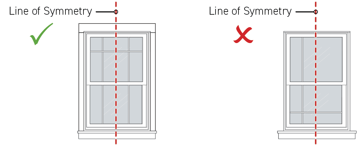
Sec. 3D.9.2. Upper Stories
Intent
The intent of the standards of this Section (Upper Stories) is to ensure projects are designed with upper story windows that contribute to the established architectural character of surrounding neighborhoods or districts.
Applicability
Upper story standards apply to new construction, a major remodel, or an exterior modification when the applied Character Frontage District (Div. 3B.9.) requires upper story transparency on facades pursuant to Sec. 3A.2.2.B.3. (Frontage Applicable Facades) and Sec. 3A.2.2.B.4. (Frontage Applicable Building Depth).
Standards
General
Standards
Applicable upper story facades shall provide at least the minimum transparency specified in the applied Character Frontage District (Div. 3B.9.).
Applicable upper story facades shall provide no more than the maximum transparency specified in the applied Character Frontage District (Div. 3B.9.).
All transparent area shall meet the standards of Sec. 3C.4.1.C. (Standards).
Measurement
Window Recession
Symmetrical Lite Pattern
Sill
The bottommost horizontal exterior surface of a window opening including a ledge or other architectural detail that projects from the surrounding building facade.
Standards
When required by the applied Frontage District (Part 3B.), all windows provided on applicable facades shall include a sill, ledge or comparable architectural detail located at the bottommost exterior surface of a window opening.
Required sills shall project a minimum of one inch beyond the immediately surrounding building facade.
Required sills shall have a width of no less than the window opening.
Measurement
Sills are measured as "provided" or "not provided" based on the compliance of all applicable windows with the standards of subparagraph a above.
Horizontal Sliding Windows
Vinyl Windows
Exceptions
Upper story transparency standards do not apply to parking structure facades unless the applied Development Standards District (Part 4B.) requires the facade to be wrapped.
Relief
Up to a 15 percent increase in the total allowed upper story transparent area may be granted in accordance with Sec. 13B.5.2. (Adjustment).
A deviation up to 15 percent from upper story transparency dimensional standards may be granted in accordance with Sec. 13B.5.2. (Adjustment).
Deviation from any upper story transparency standard may be granted as a variance in accordance with Sec. 13B.5.3. (Variance).
Div. 3D.10. Exterior Materials
Sec. 3D.10.1. Principal Material Coverage
Principal material coverage is defined as the building products used as the primary exterior wall finish materials of the exterior building facade.
Intent
The intent of the standards of this Section (Principal Material Coverage) is to visually unify the facade with a dominant material and ensure that building facades are finished with materials that contribute to the established architectural character of surrounding neighborhoods or districts.
Applicability
Principal material coverage standards apply to new construction, a major remodel, or an exterior modification. When the principal material coverage standards apply, the standards apply to facades pursuant to Sec. 3A.2.2.B.3. (Frontage Applicable Facades) and any build-to applicable story as specified by the applied Character Frontage District (Div. 3B.9.), and any portion of the frontage applicable facade located above the last provided story where the number of stories provided for any building is less than the specified build-to applicable stories.
Standards
General
The total percentage of applicable facade area finished in a primary material shall be no less than the minimum principal material coverage specified by the applied Character Frontage District (Div. 3B.9.).
Only exterior material options specified by the applied Character Frontage District (Div. 3B.9.) may be used as a primary material.
Only one primary material may used to meet the principal material coverage standard.
Exterior Material Options
For exterior material options standards, see Sec. 3D.10.3. (Exterior Material Options).
Measurement
Principal material coverage is calculated for each building width separately.
The principal material coverage percentage is the facade area covered in a principal material divided by the total applicable facade area.
The principal material coverage is measured as compliant or non-compliant based on whether it meets the standards and definition of one of the allowed exterior material options specified by the applied Frontage District (Part 3B.).
Exceptions
Principal material coverage standards do not apply to windows nor door openings.
Relief
Up to a 10 percent reduction to the total required facade area finished in an allowed primary exterior material may be granted in accordance with Sec. 13B.5.2. (Adjustment).
Deviation from any principal material coverage standard may be granted as a variance in accordance with Sec. 13B.5.3. (Variance).
Sec. 3D.10.2. Accessory Material Coverage
Accessory material coverage is defined as the building products used as an exterior wall finish material to accent or support the principal material.
Intent
The intent of the standards of this Section (Accessory Material Coverage) is to visually unify the facade with a consistent material palette and ensure that building facades are finished with materials that contribute to the established architectural character of surrounding neighborhoods or districts.
Applicability
Accessory material coverage standards shall apply to new construction, a major remodel, or an exterior modification. When the accessory material coverage standards apply, the standards apply to any facade pursuant to Sec. 3A.2.2.B.3. (Frontage Applicable Facades) and any build-to applicable story as specified by the applied Character Frontage District (Div. 3.9.), and any portion of the frontage applicable facade located above the last provided story where the number of stories provided for any building is less than the specified build-to applicable stories.
All exterior materials cumulatively covering between five percent and 30 percent of the total applicable facade area are considered an accessory material and shall comply with all accessory material coverage, exterior material options, and number of accessory material standards.
Standards
General
The total percentage of applicable facade area finished in an accessory material shall not exceed the maximum accessory material coverage specified by the applied Character Frontage District (Div. 3B.9.).
Only exterior material options specified by the applied Character Frontage District (Div. 3B.9.) may be used as an accessory material.
Exterior Material Options
For exterior material options standards, see Sec. 3D.10.3. (Exterior Material Options).
Number of Accessory Materials
Individual accessory materials may not exceed the maximum number of accessory materials specified by the applied Character Frontage District (Div. 3B.9.).
Measurement
Accessory material coverage is calculated for each building width separately.
Accessory material coverage percentage is the facade area covered in the accessory material product divided by the total applicable facade area.
Accessory material coverage is measured as compliant or non-compliant based on whether it meets the standards and definition of one of the exterior material options specified by the applied Character Frontage District (Div. 3B.9.).
Exceptions
Accessory material coverage standards do not apply to windows nor door openings.
Relief
Up to a 10 percent increase in the total allowed facade area finished in a secondary exterior material may be granted in accordance with Sec. 13B.5.2. (Adjustment).
Deviation from any accessory material standard may be granted as a variance in accordance with Sec. 13B.5.3. (Variance).
Sec. 3D.10.3. Exterior Material Options
Exterior material options is defined as building products allowed for use as primary or accessory exterior wall finish material.
Intent
The intent of the standards of this Section is to ensure that building facades are finished with materials that contribute to the established architectural character of surrounding neighborhoods or districts.
Applicability
Exterior material options standards apply to all exterior materials provided and shall comply with principal material coverage or accessory material coverage standards as specified by the applied Character Frontage District (Div. 3B.9.).
Standards
General
Proposed principal and accessory materials shall meet all standards and definitions of one of the exterior material options specified by the applied Character Frontage District (Div. 3B.9.) to comply with principal material coverage and accessory material coverage standards.
Exterior Material Options
a.Brickwork
Courses of rectangular masonry units made of hardened clay, laid with mortar exposed between bricks. Examples include solid brick construction, brick veneer and thin brick veneer. Other products required for installation that are visually incidental to the brick are also included.

Intent
To provide structures with a human scale, durability, and a connection to local history. The profile of brickwork creates a pattern of channels along the mortar beds and perpends providing shadow line effects and texture reflecting the scale of the individual brick units. The size of the brick units are of a commonly recognized scale related to its manual assembly which naturally helps observers relate to the overall scale of the structure and recognize the building as a result of tangible human activities rather than machined or synthetic installations. Brick assemblies provide lasting durability against weather and wear, reducing maintenance demands. Used as an exterior building material in some of Los Angeles most treasured historic buildings, brickwork connects observers to local history.
Dimensional Standards
i.Individual brick units shall have a height of between 1.5 and 8 inches.
ii.Individual brick units shall have a width of between 3.5 and 16 inches.
b.Stonework
Stacked rocks quarried and worked into a specific size and shape for use as a building material. Solid stone includes mortar and other products required for installation that are visually incidental to the stone product. Examples include solid stone construction, stone veneer, and thin stone veneer. Solid stone excludes heavy aggregate concrete, terrazzo, engineered stone products, and comparable materials.

Intent
To provide structures with a human scale, durability, and a connection to nature and local history. The profile of stonework provides dynamic shadow line effects relating to the scale of individual stones, helping observers to relate to the overall scale of the structure. The organic textures and deep natural colors of exposed stone faces provide observers with a connection to nature. Solid stone assemblies provide lasting durability against weather and wear, reducing maintenance demands. Used as an exterior building material in some of Los Angeles most treasured historic buildings, solid stone assemblies connect observers to local history.
Dimensional Standards
n/a
c.Concrete
A cement based product either poured-in-place or pre-cast in a form or mold. Concrete includes engineered masonry products set in resin or cement such as terrazzo, terracotta, CMU, breeze block, and exposed columns and beams. Other products required for installation that are visually incidental to the concrete product are also included. Concrete excludes fiber cement products, brick, EFIS, and stucco.

Intent
To provide structures with the lasting durability and a sense of weight and permanence through use of concrete.
Dimensional Standards
Not applicable
d.Metal
Metal products designed and intended for architectural purposes. Examples include exposed structural steel, architectural metal panels, and decorative metal products. Other products required for installation that are visually incidental to the metal product are also included.

Intent
To provide structures with the lasting durability and sense of permanence through use of metal.
Dimensional Standards
Not applicable
e.Wood
Tree-based products milled into a particular shape and size for use as an exterior building material. Examples include wood panels, structural lumber such as cross laminated timber and glulam beams, plank siding, and shingles. Wood excludes products with exposed faces composed substantially of wood chips, particles, and fibers. Examples include structural composite lumber like PSL, LSL, and OSL, and composite panel products like OSB, fiberboard, and particleboard. Wood also excludes faux-wood products such as vinyl, aluminum, and fiber cement siding. Other products required for installation that are visually incidental to the wood product are also included.

Intent
To provide structures with a connection to nature and local history through use of wood. The organic patterns and warm natural colors of exposed wood provide observers with a connection to nature. Used as an exterior building material in some of Los Angeles most treasured historic buildings, wood products connect observers to local history.
Dimensional Standards
Not applicable
f.Glazed Tile
Ceramic tile having porcelain or natural clay body, glazed for surfacing walls, typically attached to an exterior wall with mortar and finished by filling joints between tiles with a cement- or resin-based grout product. Examples include small or large format tile and structural facing tile. Other products required for installation that are visually subordinate to the tile product are also allowed. Glazed tile excludes terracotta and other non-ceramic tile products.

Intent
To provide structures with a human scale, durability, and a connection to local history. The profile of glazed tile assemblies provides a regular pattern of channels along grout joints, creating shadow line effects and texture reflecting the scale of the individual tile units. Glazed tile assemblies provide lasting durability against weather and wear, reducing maintenance demands. Used as an exterior building material in some of Los Angeles most treasured historic buildings, glazed tile assemblies connect observers to local history with their familiar luster and sheen.
Dimensional Standards
Not applicable
g.Horizontal Plank Siding
Courses of long, thin horizontal boards, often overlapping or interlocking horizontally but also including open joint systems. Horizontal plank siding includes clapboard, bevel, lap, weatherboard, shiplap, and rain screen siding and may be composed of a wide range of materials including wood, fiber cement products, and vinyl. Horizontal plank cladding excludes textured panel products with unit sizes exceeding 10 inches in height regardless of the pattern or texture.

Intent
To provide a human scale to buildings. The profile of the siding assembly creates a pattern of horizontal channels providing deep shadow line effects and texture reflecting the scale of the individual board units. The scale of the board units are of a commonly recognized scale related to its manual assembly which naturally helps observers to understand and relate to the overall scale of the structure and recognize the building as a result of tangible human activities rather than machined or synthetic installations.
Dimensional Standards
i.Individual board units shall have a height of between 2 and 10 inches.
ii.Overlapping or interlocking board units may have a height greater than 10 inches provided no board unit is exposed for a continuous height of more than 10 inches.
iii.Open joint systems shall not provide a gap greater than 3/4" between board units.
h.Vertical Plank Siding
Courses of long, thin vertical boards, often overlapping or interlocking vertically but also including open joint systems. Vertical plank siding includes, board and batten, tongue and groove, shiplap, and rain screen siding and may be composed of a wide range of materials including wood, fiber cement products, and vinyl. Vertical plank cladding excludes textured panel products with continuous reveal dimensions greater than 16 inches in width regardless of the pattern or texture.

Intent
To provide a human scale to buildings. The profile of the siding assembly creates a pattern of vertical channels providing deep shadow line effects and texture reflecting the scale of the individual board units. The scale of the board units are of a commonly recognized scale related to its manual assembly which naturally helps observers to understand and relate to the overall scale of the structure and recognize the building as a result of tangible human activities rather than machined or synthetic installations.
Dimensional Standards
i.Individual board units shall have a width of between 1 and 16 inches.
ii.Overlapping or interlocking board units may have a width greater than 16 inches provided no board unit is exposed for a continuous width of more than 16 inches.
iii.Open joint systems shall not provide a gap greater than 3/4" between board units.
i.Shingle Siding
Courses of short, thin building materials, overlapping horizontally. Shingle siding includes square, round, half-cove, and hexagon, shaped shingles and be composed of a wide range of materials including cedar, cementitious fiberboard, and vinyl. Shingle siding excludes asphalt roofing shingles and textured panel products with continuous reveal dimensions greater than 24 inches in width or 12 inches in height regardless of the pattern or texture.
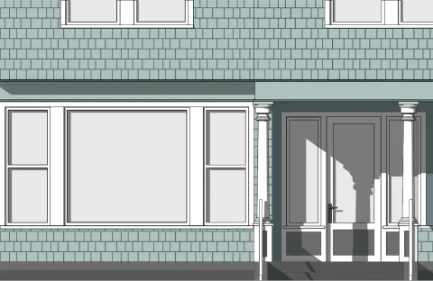
Intent
To provide a human scale to buildings. The profile of the shingle assembly creates a pattern of vertical and horizontal channels providing deep shadow line effects and texture reflecting the scale of the individual shingle units. The scale of the shingle units are of a commonly recognized scale related to its manual assembly which naturally helps observers to understand and relate to the overall scale of the structure and recognize the building as a result of tangible human activities rather than machined or synthetic installations.
Dimensional Standards
i.Individual shingle units shall have a width of between 2 and 24 inches.
ii.Individual shingle units shall have a height of between 2 and 12 inches.
iii.Shingle units may have a width greater than 24 inches or a height greater than 12 inches provided no individual shingle is exposed for a continuous width of more than 24 inches or a continuous height of more than 12 inches.
j.Stucco
A building material composed primarily of Portland cement, finely ground limestone, sand and water, applied directly onto a building over a reinforcing base mesh. Stucco excludes textured panel products and synthetic stucco such as EIFS, elastomeric stucco, and acrylic stucco.

Intent
To provide structures with durability and a connection local history. Stucco provides lasting durability against weather and wear, reducing maintenance demands. Used as an exterior building material in some of Los Angeles most treasured historic buildings, stucco connects observers to local history.
Dimensional Standards
Not applicable
Measurement
The height of individual board, brick, or shingle unit is measured as the greatest dimension from one end of the unit to the opposite end of the unit, measured vertically and based on the proposed installation pattern.
The width of individual board, brick, or shingle unit is measured as the greatest dimension from one end of the unit to the opposite end of the unit, measured horizontally and based on the proposed installation pattern.
Exposed width is measured as the largest horizontal dimension of a board or shingle unit that is uninterrupted by either, another board or shingle covering the first unit, or a gap or break in the board or shingle unit, for the full height of the unit.
Exposed height is measured as the largest vertical dimension of a board or shingle unit that is uninterrupted by either, another board or shingle covering the first unit, or a gap or break in the board or shingle unit, for the full height of the unit.

Gap between board units is measured as the distance between board units at the widest point.
Relief
Deviation from exterior material option standards may be granted in accordance with Sec. 13B.5.1. (Alternative Compliance).
Up to a 10 percent modification to any exterior material option dimensional standard may be granted in accordance with Sec. 13B.5.2. (Adjustment).
Deviation from any exterior material option standard may be granted as a variance in accordance with Sec. 13B.5.3. (Variance).


Div. 3D.11. Roof Design
Sec. 3D.11.1. Roof Form
Roof form is defined as the shape of the external upper covering of a building, including the frame for supporting the roofing.
Intent
The intent of the standards of this Section (Roof Design) is to ensure that building forms contribute to the established architectural character of surrounding neighborhoods or districts.
Applicability
Roof form standards apply to new construction, a major remodel, or an exterior modification when the applied Character Frontage District (Div. 3B.9.) requires a primary roof form on any frontage lot line-facing buildings.
A minimum of 70 percent of the total roof area of each applicable building or structure shall meet roof form standards, measured horizontally.
Standards
General
All building and structures shall have a roof form listed as a roof form option in the applied Frontage District (Part 3B.).
Roof Form Options
Flat
A roof subject to the “flat” option shall have a maximum pitch of 2:12 (two inch of vertical rise for every 12 inches of horizontal span) or less. Flat roof forms include roofs with parapets up to six feet in height.
Pitched
A roof subject to the “pitched” option shall be composed of two or more sloping planes where all roof planes slope up from the exterior perimeter of the building or structure and connect with another roof plane at a central ridge. All roof planes required to meet this standard shall have pitch between a minimum of 3:12 (three inches of vertical rise for every 12 inches of horizontal span) and a maximum of 16:12 (16 inches of vertical rise for every 12 inches of horizontal span).

Measurement
Roof pitch is measured by calculating a roof's vertical rise in inches divided by a foot of its horizontal span and is represented as a ratio.
Roof form is measured as compliant or non-compliant based on whether it meets the standards and definition of one of the roof form options allowed by the applied Frontage District (Part 3B.).
Relief
Up to a 10 percent reduction in the total required roof area having an allowed roof form may be granted in accordance with Sec. 13B.5.2. (Adjustment).
A deviation from roof form dimensional standard up to 10 percent may be granted in accordance with Sec. 13B.5.2. (Adjustment).
Deviation from any roof form standard may be granted as a variance in accordance with Sec. 13B.5.3. (Variance).

Sec. 3D.11.2. Roof Materials
Intent
The intent of the standards of this Section (Roof Materials) is to ensure that a building's roof finishing materials contribute to the established architectural character of surrounding neighborhoods or districts.
Applicability
This Section (Roof Materials) applies to new construction, a major remodel, or an exterior modification. When roof materials standards apply, the standards apply to all portions of a required primary roof form pursuant to Sec. 3D.11.1. (Roof Form) on any frontage lot line-facing buildings on a lot.
Standards
Only roof materials specified by the applied Frontage District (Part 3B.) shall be used to finish an applicable roof.
Measurement
Roof materials are measured as compliant or non-compliant based on whether all applicable roofs meet the roof materials standards.
Exceptions
Roof material standards do not apply to accessory roof forms.
Relief
Up to a 10 percent reduction in the total required roof area finished of an allowed roof material may be granted in accordance with Sec. 13B.5.2. (Adjustment).
Deviation from roof materials standards may be granted as a variance in accordance with Sec. 13B.5.3. (Variance).
Sec. 3D.11.3. Roof Overhang
Roof overhang is defined as the portion of a roof extending beyond a building’s exterior walls.
Intent
The intent of the standards in this Section (Roof Overhang) is to ensure that a building's roof design contributes to the established architectural character of surrounding neighborhoods or districts.
Applicability
Roof overhang standards apply to new construction, a major remodel, or exterior modification when specified by the applied Character Frontage Districts (Div. 3B.9.). Roof overhang standards apply to any portion of a roof subject to Sec. 3D.11.1. (Roof Form).
Standards
The roof plane shall extend horizontally beyond the building footprint by no less than the minimum roof overhang dimension specified by the applied Character Frontage District (Div. 3B.9.) for all portions of the perimeter of the building footprint.
Measurement
Roof overhang is measured horizontally and perpendicular to the building facade from the face of the outermost building facade to the outer edge of the roof plane for the full perimeter of the building or structure.
Relief
Up to a 15 percent reduction to the minimum roof overhang dimension may be granted in accordance with Sec. 13B.5.2. (Adjustment).
A deviation from roof overhang standards beyond those available by Adjustment, above, may be granted as a variance in accordance with Sec. 13B.5.3. (Variance).