Use Finder
Part 3C. General Frontage Rules
Div. 3C.1. Build-To
Sec. 3C.1.1. Applicable Stories
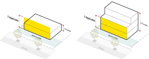
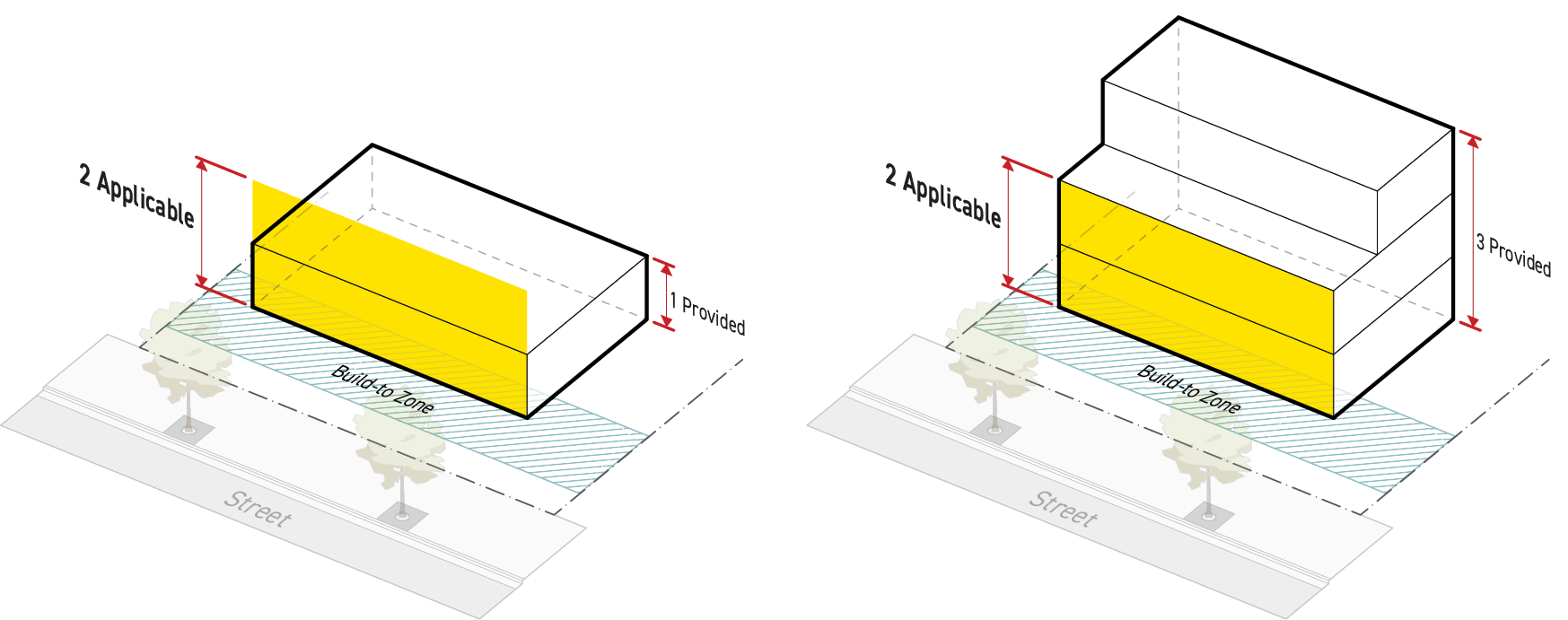
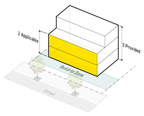
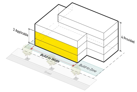
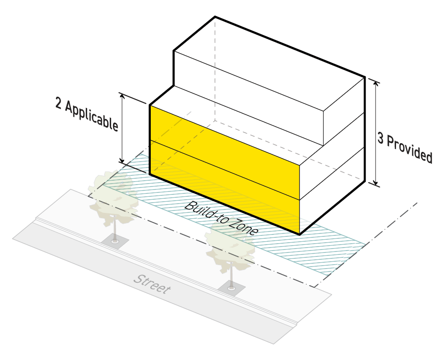
Applicable stories is defined as the number of stories that are required to meet build-to standards.
Intent
The intent of the standards of this Section (Applicable Stories) is to ensure that ground stories of buildings, and upper stories where appropriate, are located in a consistent manner along the street.
Applicability
Applicable stories standards apply to new construction of any portion of a building or structure, or a whole building or structure. When the applicable stories standards apply, the standards apply to any part of the building or structure that is required to meet the standards of Sec. 3C.1.2. (Build-To Depth) and the standards of Sec. 3C.1.3. (Build-To Width).
Standards
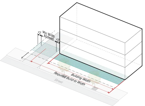
Where minimum applicable stories are required, build-to standards apply to the ground story and any additional story provided on a lot, up to, and including, the minimum build-to applicable stories.
Measurement
For measuring height in stories, see Sec. 2C.4.3. (Height in Stories).
Relief
A reduction of one story from the number of applicable stories may be granted in accordance with Sec. 13B.5.2. (Adjustment).
A reduction in number of applicable stories may be granted as a variance in accordance with Sec. 13B.5.3. (Variance).
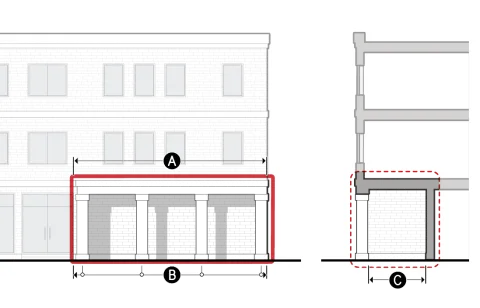
Sec. 3C.1.2. Build-To Depth
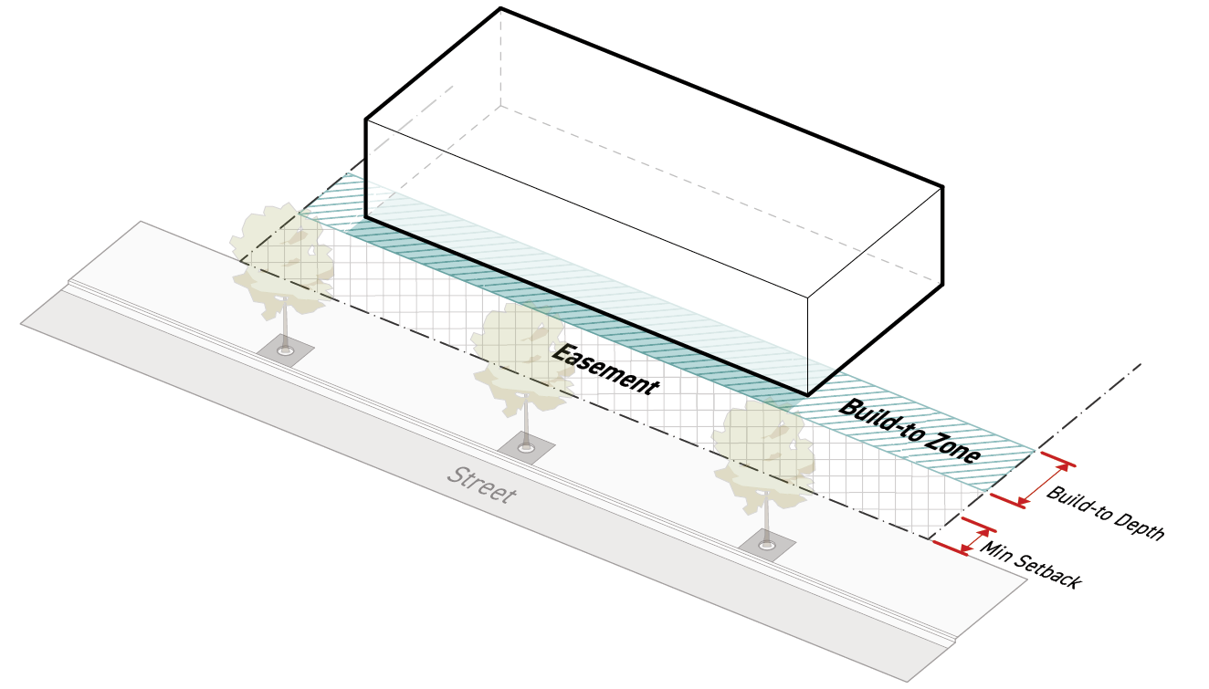
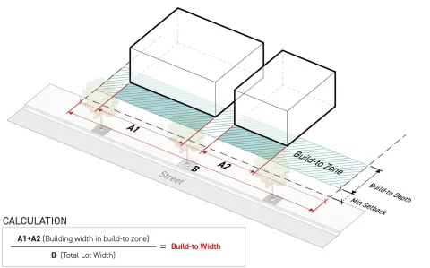
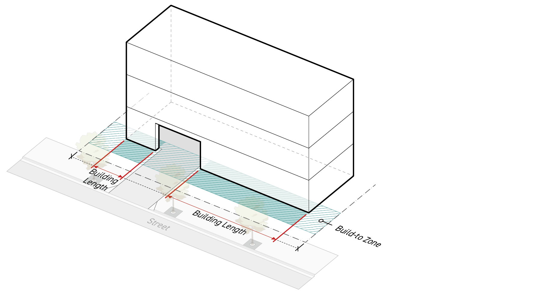
Build-to depth is defined as the depth of the build-to zone starting at the minimum building setback and continuing inward for the maximum build-to depth for the full width of the lot.
Intent
The intent of the standards of this Section (Build-To-Depth) is to regulate buildings along the public realm and to create a consistent street wall.
Applicability
Build-to depth standards apply to new construction. When build-to depth standards apply, they apply to all portions of buildings and structures required to satisfy the standards of Sec. 3C.1.3. (Build-To Width) and the standards of Sec. 3C.1.1. (Applicable Stories).
Standards
The build-to zone shall be no deeper than the maximum build-to depth of the applied Frontage District (Part 3B.).
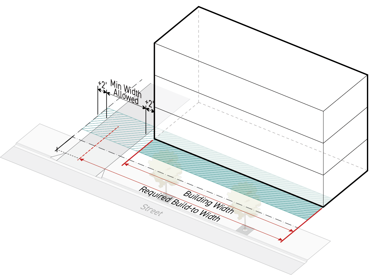
Buildings shall occupy the build-to zone for at least the minimum required build-to width.
Once the minimum build-to width standard has been satisfied, buildings and structures may occupy the area behind the build-to zone.
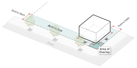
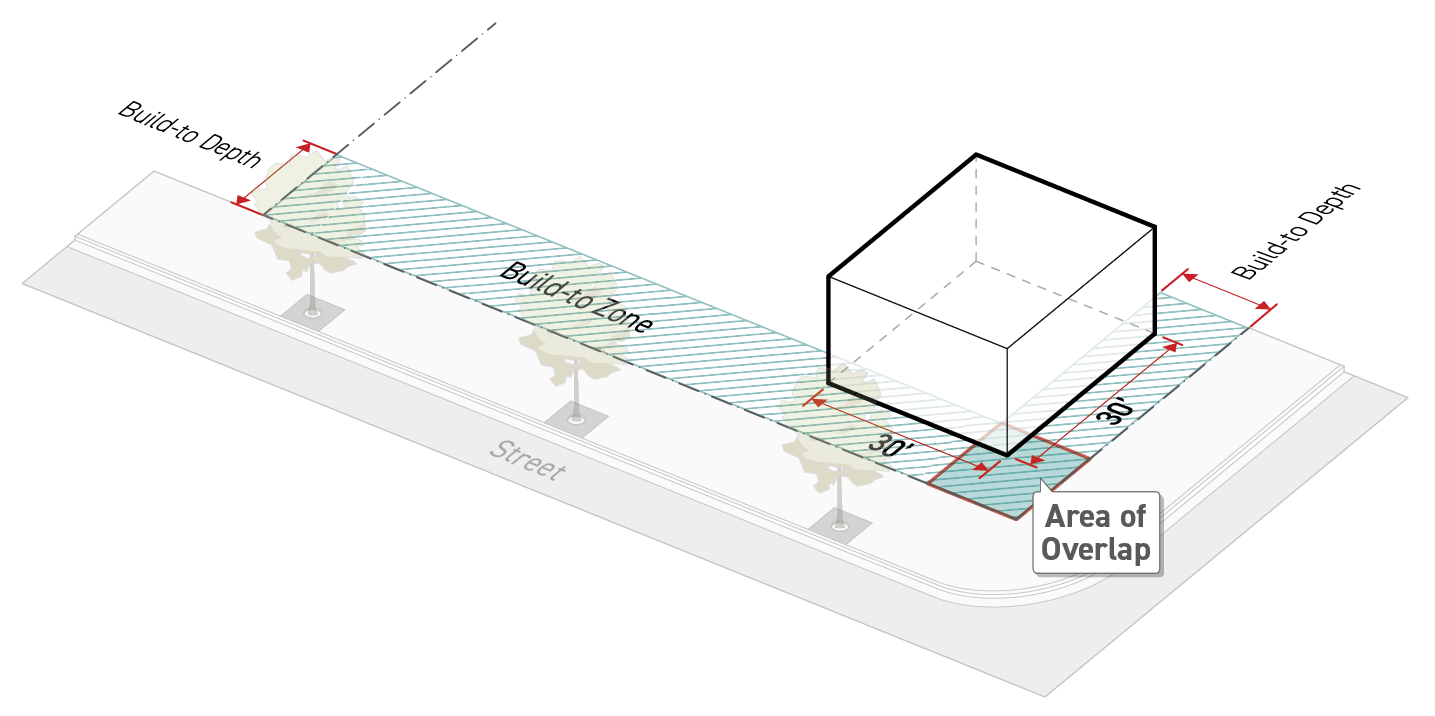
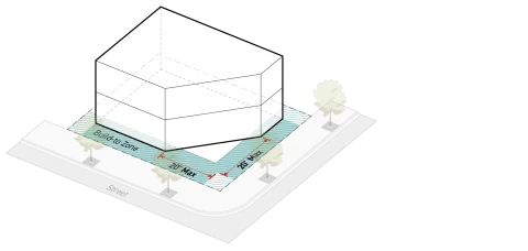
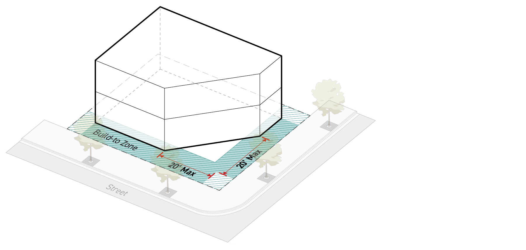
On a corner lot where intersecting frontage lot lines have build-to requirements, a building shall occupy the portion of the lot area where the build-to zones of the two intersecting frontage lot lines overlap, as described below:
The building shall occupy the build-to zones for both frontage lot lines for a minimum of 30 feet from the corner. This building width counts toward the required build-to width for both frontage lot lines.
This standard does not apply when a pedestrian amenity space occupies some portion of the area of overlap and is being used as a pedestrian amenity allowance. See Sec. 3C.1.4. (Pedestrian Amenity Allowance).
Measurement
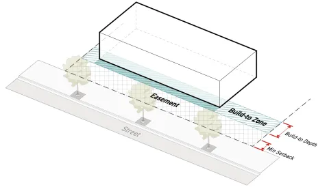
The build-to depth is measured perpendicular to the frontage lot line starting from the minimum building setback and continuing inward away from the frontage lot line.
Where a lot includes an easement that abuts the frontage lot line and the easement is deeper than the minimum building setback, the applicant may choose to measure the required build-to depth from the interior edge of the easement rather than the lot line.
For a lot affected by a public access easement, see Sec. 14.2.17.B.3. (Build-To Depth).
Exceptions
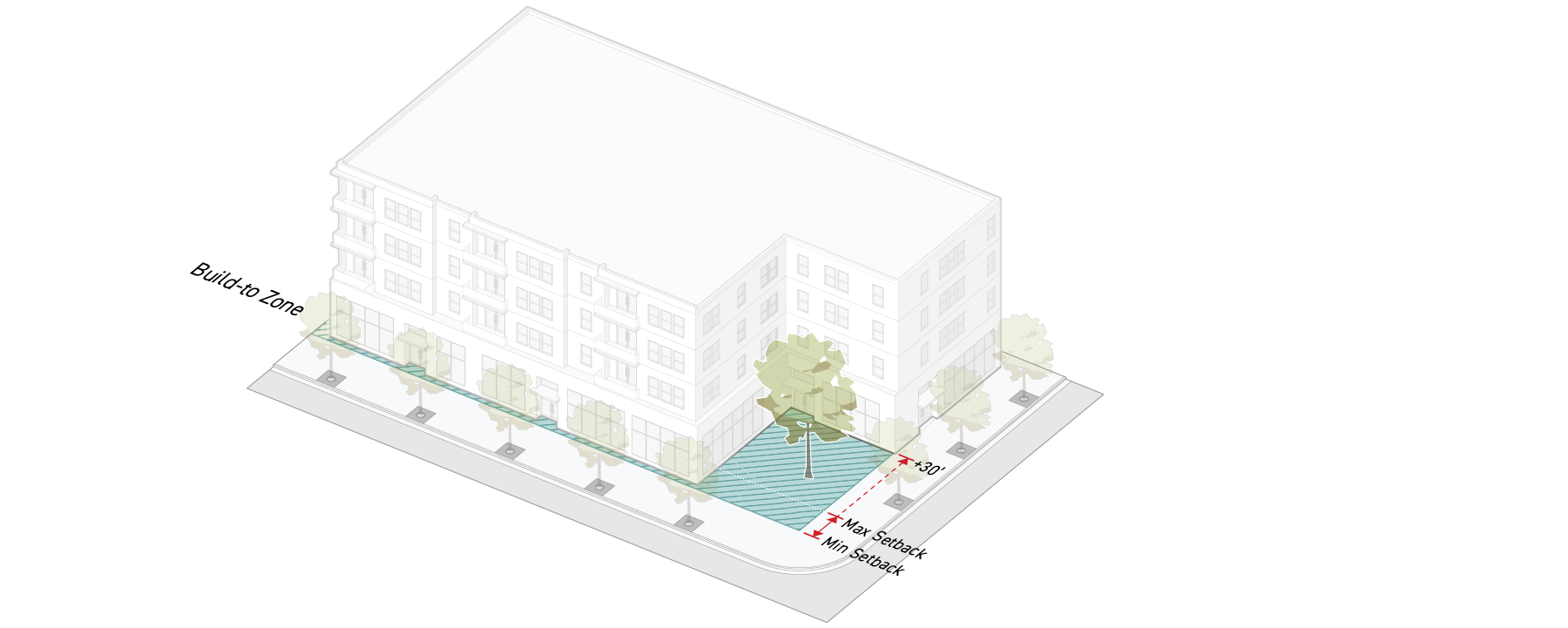
To preserve existing trees that meet minimum size requirements for a small species tree, the Department may increase the build-to depth beyond the maximum allowed by the applied Frontage District to the minimum depth necessary to protect the tree, but by no more than 30 feet pursuant to Sec. 13B.3.1. (Administrative Review).
See Sec. 12.3.1. (Build-To Exceptions).
Relief
An increase in build-to depth of 20 percent may be granted in accordance with Sec. 13B.5.2. (Adjustment).
A deviation from maximum build-to depth may be granted as a variance in accordance with Sec. 13B.5.3. (Variance).
Sec. 3C.1.3. Build-To Width
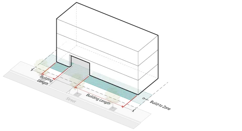
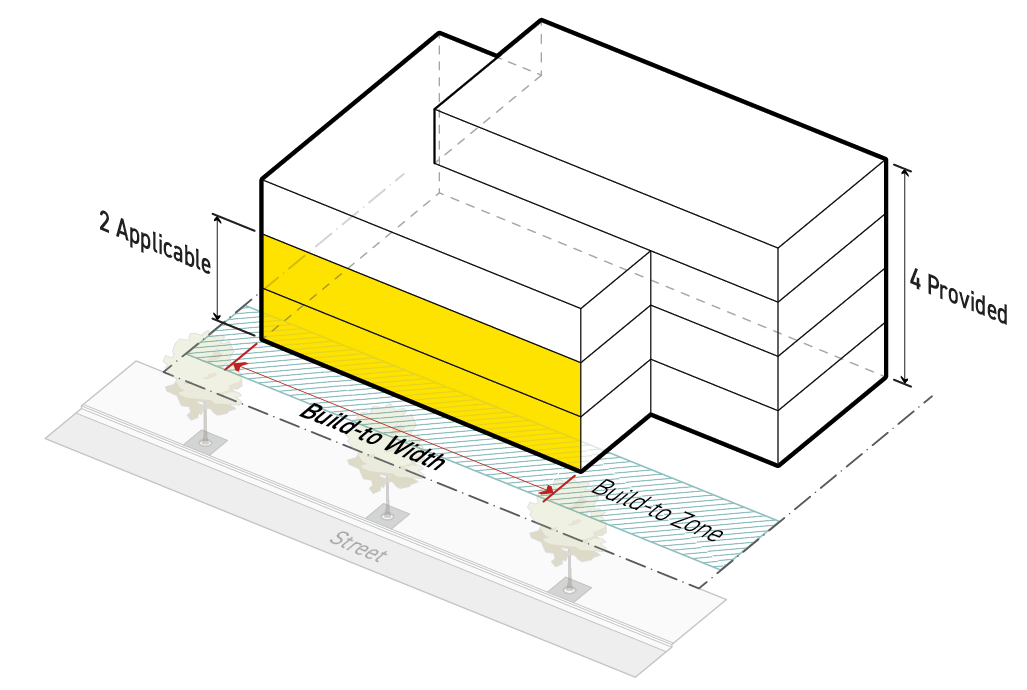
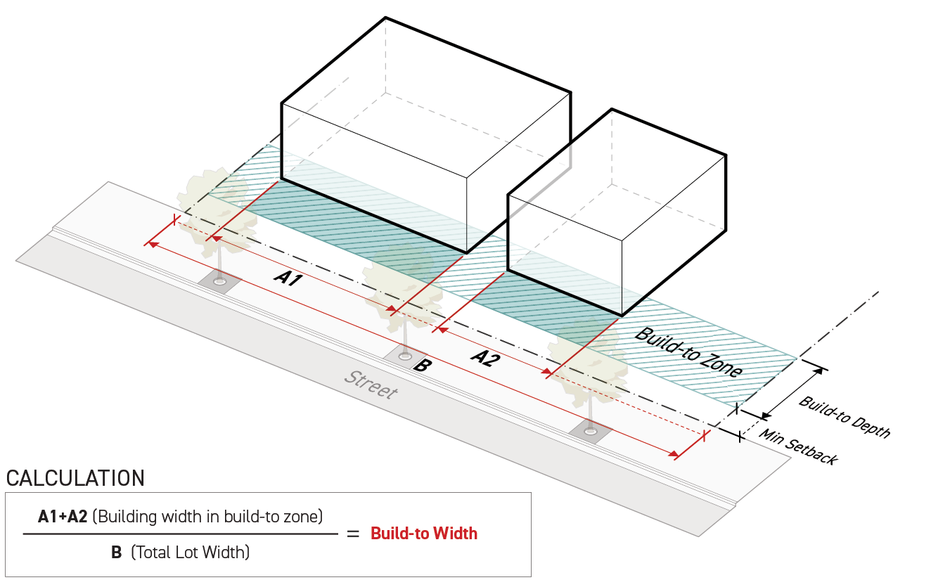
Build-to width is defined as the cumulative building width that shall occupy the build-to zone, relative to the width of the lot at the frontage lot line.
Intent
The intent of the standards of this Section (Build-To-Width) is to ensure that buildings enclose the public realm with a legible and consistent street wall, spatially defining an outdoor room, and to promote a strong visual and physical connection between uses inside buildings and the public realm.
Applicability
Build-to width standards apply to new construction and are subject to the following:
Where a minimum height is specified in the applied Form District (Part 2B.), build-to width standards apply to all above-grade stories up to the minimum height in stories standard in accordance with Sec. 2C.4.3. (Height in Stories).
Where an applicable stories standard exists, build-to width standards apply to all stories located above-grade up to the applicable stories.
Where both an applicable stories standard and a minimum height standard are specified, build-to width standards apply to whichever standard requires the greatest number of stories located in the build-to zone.
Where no applicable stories standard is specified in the applied Frontage District (Part 3B.) and no minimum height standard is specified in the applied Form District (Part 2B.), build-to width standards apply only to the ground story.
Standards
Building(s) shall occupy the build-to zone for a cumulative width no less than that specified by the applied Frontage District (Part 3B.).
On a corner lot, a chamfered corner no more than 20 feet in width along both street lot lines qualifies as building width in the build-to zone for all applicable stories even where it extends outside of the build-to zone. Chamfered corner width is measured parallel to the frontage lot line.
Portions of building width providing motor vehicle access to a motor vehicle use area through the ground story of a building do not qualify as building width in the build-to zone.
Measurement
The build-to width is a percentage measured as the sum of the widths of all portions of buildings occupying the build-to zone divided by the total lot width.
Building width is measured parallel to the frontage lot line. For measuring building width on a lot with a curved or irregular lot line, see Sec. 14.2.14. (Irregular Lot Lines).
Lot width is measured along the frontage lot line. For measuring width of a lot with a curved or irregular lot line, see Sec. 14.2.14. (Irregular Lot Lines).
Exceptions
Pedestrian amenity space counts toward required minimum build-to width in accordance with Sec.3C.1.4. (Pedestrian Amenity Allowance).
A building break that includes an open space meeting the design standards for pedestrian amenity space in Sec. 2C.3.3.C.2. (Pedestrian Amenity Space) counts toward the minimum build-to width required by the applied Frontage District (Part 3B.) according to Sec. 3C.1.4. (Pedestrian Amenity Allowance).
Where vehicle access is taken through the frontage lot line based on the automobile access package in Sec. 4C.2.1. (Automobile Access Packages) as specified by the applied Development Standards District (Part 4B.), and providing vehicle access prevents a building from achieving the required build-to width, a reduced build-to width may be allowed. However, the portion of the lot in the build-to zone used for vehicle access shall be no wider than the minimum required drive aisle width plus an additional four feet of width for clearance. See Div. 4C.2. (Automobile Access).
See Sec. 12.3.1. (Build-To Exceptions).
Relief
Up to a 10 percent reduction to the total required width of a building occupying the build-to zone may be granted in accordance with Sec. 13B.5.2. (Adjustment).
A reduced minimum build-to width may be granted as a variance in accordance with Sec. 13B.5.3. (Variance).
Sec. 3C.1.4. Pedestrian Amenity Allowance
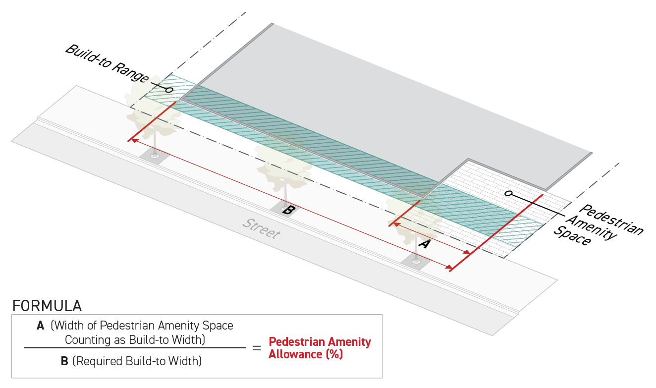
Pedestrian amenity allowance is defined as the width of pedestrian amenity space in the build-to zone that can be counted toward the build-to width requirement.
Intent
The intent of the standards of this Section (Pedestrian Amenity Allowance) is to promote the creation of active, human-scale outdoor spaces as an extension of the sidewalk, providing visual interest and vitality to the amenity space as well as the public realm. The pedestrian amenity allowance provides flexibility to building and site design while maintaining standards essential for ensuring all projects contribute to defining a consistent and legible street wall.
Applicability
Pedestrian amenity allowance standards apply to new construction subject to a pedestrian amenity allowance maximum in the applied Frontage District (Part 3B.).
Pedestrian amenity allowance standards apply to all portions of a building or structure required to meet the standards of Sec. 3C.1.3. (Build-To Width) and Sec. 14.2.6.C. (Pedestrian Amenity & Public Amenity-Facing Facades), and portions of the lot between the building and the frontage lot line for the width of the pedestrian amenity space provided.
Standards
Where the applied Frontage District (Part 3B.) specifies a pedestrian amenity allowance, pedestrian amenity spaces may be provided as a substitute for a portion of the required build-to width up to the maximum percentage specified, provided they meet the following standards:
Meets the standards of Sec. 2C.3.3.C. (Standards).
Pedestrian amenity spaces may be wider than the maximum allowed pedestrian amenity allowance, however, any part of the pedestrian amenity space width that exceeds the allowed pedestrian amenity allowance does not count toward the required building width in the build-to zone.
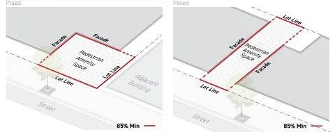
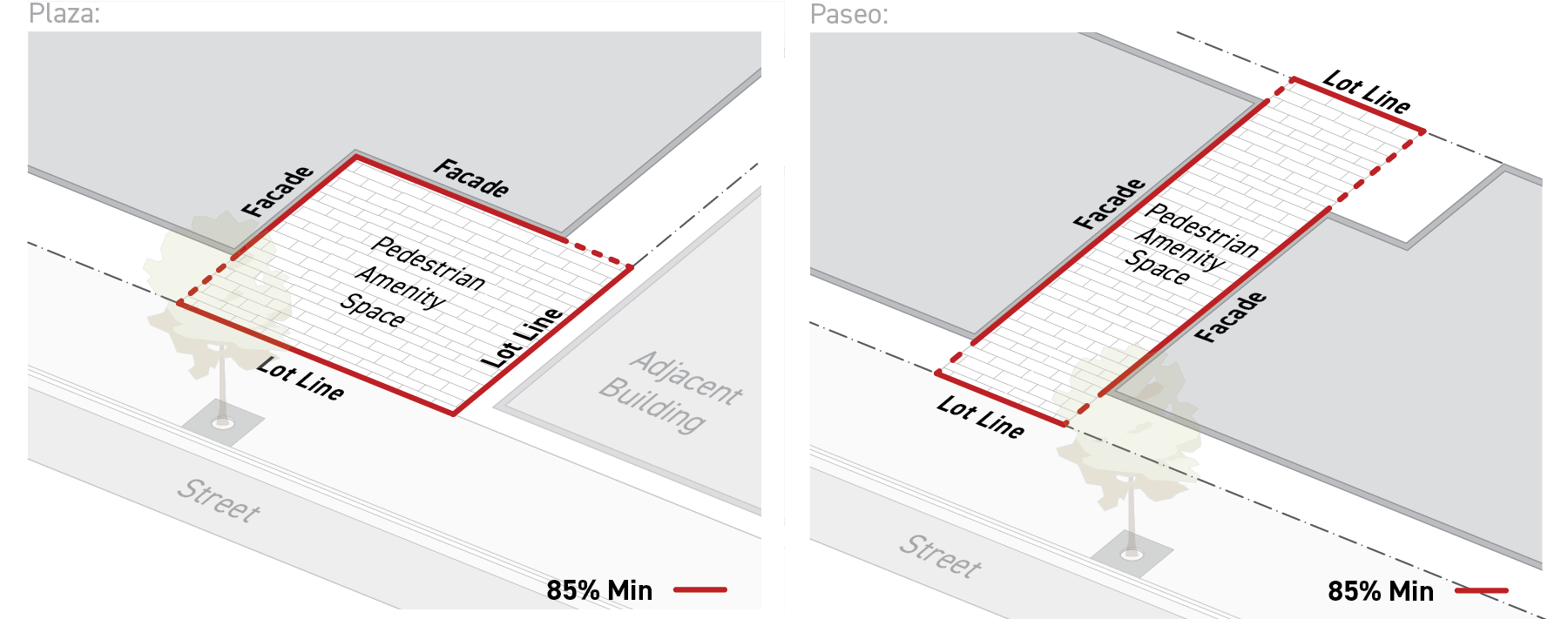
At least 85 percent of the pedestrian amenity space perimeter shall abut a lot line or a facade meeting the standards of the applied Frontage District (Part 3B.) as specified for the abutting frontage lot line. Where the pedestrian amenity space abuts multiple frontage lot lines, the standards specified for the frontage lot line abutting the pedestrian amenity space for the greatest length apply.
Measurement
Pedestrian amenity allowance is measured as the cumulative width of pedestrian amenity spaces occupying the build-to zone divided by the required build-to width.
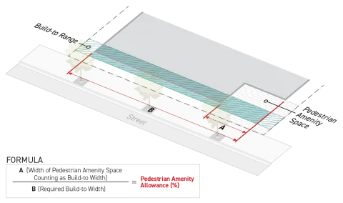
Pedestrian amenity space width is measured parallel to the frontage lot line. For measuring pedestrian amenity space width along a curved or irregular lot line, see Sec. 14.2.14. (Irregular Lot Lines).
For measuring the required build-to width, see Sec. 3C.1.3. (Build-To Width).
For a lot affected by a public access easement, see Sec. 14.2.17.B.4. (Pedestrian Amenity Allowance).
Relief
Up to a 10 percent increase in the allowed total width of pedestrian amenity allowance may be granted in accordance with Sec. 13B.5.2. (Adjustment).
A deviation from any pedestrian amenity allowance dimensional standard of up to 10 percent may be granted in accordance with Sec. 13B.5.2. (Adjustment).
A reduced minimum build-to width may be granted as a variance in accordance with Sec. 13B.5.3. (Variance).
Div. 3C.2. Parking
Sec. 3C.2.1. Parking Setback
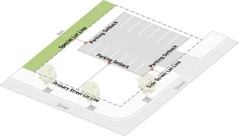
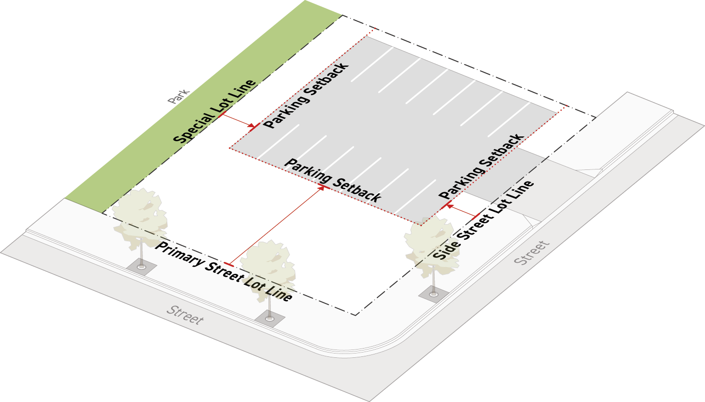
Parking setback is defined as an area on a lot along a frontage lot line where motor vehicle use areas are prohibited, including primary street parking setbacks, side street parking setbacks, and special lot line parking setbacks.
Intent
The intent of the standards of this Section (Parking Setback) is to minimize the impact of motor vehicle dominated areas on the public realm and to promote a comfortable, safe, engaging, and attractive streetscape with active uses and landscaping along the public realm.
Applicability
Parking setback standards apply to new construction, a major remodel, or a site modification. When parking setback standards apply, the standards apply to any areas of a lot designed and designated for a parking area or motor vehicle use area.
Standards
All applicable areas designated for motor vehicle use shall be located at or behind the required parking setback unless specifically stated as an exception in Subsection E. (Exceptions) below.
Measurement
All parking setbacks are measured perpendicular to the frontage lot line.
A primary street parking setback is measured from the minimum primary street setback and continues inward away from the frontage lot line.
A side street parking setback is measured from the minimum side street setback and continues inward away from the frontage lot line.
A special parking setback is measured from the minimum setback associated with a special lot line and continues inward away from the special lot line.
For a lot affected by a public access easement, see Sec. 14.2.17.B.5. (Parking Setback).
Exceptions
A driveway may provide access through a parking setback if:
The automobile access package specified by the applied Development Standards District (Part 4B.) allows automobile access through the frontage lot line associated with a parking setback, then a driveway may be permitted in the parking setback, and
The driveway is no wider than the minimum required width. See Div. 4C.2. (Automobile Access).
Relief
A reduction in the required parking setback up to 20 percent may be granted in accordance with Sec. 13B.5.2. (Adjustment).
A reduction in the required parking setback may be granted as a variance in accordance with Sec. 13B.5.3. (Variance).
Div. 3C.3. Landscaping
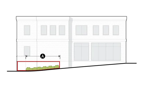
Sec. 3C.3.1. Frontage Planting Area
Frontage planting area is defined as the area in a frontage yard designated and designed for plants.
Intent
The intent of the standards of this Section (Frontage Planting Area) is to support a comfortable, attractive, and contextually appropriate streetscape along the public realm, while promoting infiltration, slowing stormwater runoff, and offsetting urban heat island effect.
Applicability
Frontage planting area standards apply to new construction, a major remodel, or a site modification, on any lot possessing yards abutting a frontage lot line.
Standards
Each frontage yard shall provide a cumulative area at least the size of the planting area required by the applied Frontage District (Part 3B.).
All required planting areas shall meet Sec. 4C.6.4.C.2. (Planting Area).
All provided plants shall meet Sec. 4C.6.4. (Plant Design & Installation).
Measurement
Frontage planting area is a percentage calculated as the cumulative planting area located in a frontage yard divided by the total frontage yard area.
For frontage yard designation, see Sec. 14.2.16. (Yards).
For a lot affected by a public access easement, see Sec. 14.2.17.B.6.(Frontage Planting Area).
Exceptions
Where there is less than three feet between the building and frontage lot line, planting area standards are not applicable.
Relief
Frontage planting area standards may be met through alternative compliance in accordance with Sec. 13B.5.1. (Alternative Compliance).
Up to a 20 percent reduction to the total required planting area may be granted in accordance with Sec. 13B.5.2. (Adjustment).
A reduction in the required planting area may be granted as a variance in accordance with Sec. 13B.5.3. (Variance).
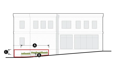
Sec. 3C.3.2. Frontage Yard Fence & Wall
Frontage yard fence & wall is defined as fences, walls, and hedges that are allowed in a frontage yard.
Intent
The intent of the standards of this Section (Frontage Yard Fence & Wall) is to balance the needs for human-scale activation and visual interest along the public realm, and to provide security and privacy for private ground story uses in a manner appropriate to context.
Applicability
Frontage yard fence & wall standards apply to a site modification involving construction or installation of fences, walls, or hedges, in a frontage yard.
Standards
General
Allowed frontage yard fence & wall types are hierarchical. Where a frontage yard fence & wall type with a higher number designator (e.g. Type A2) is allowed by the applied Frontage District (Part 3B.), all frontage yard fence & wall types having a lower number designator (e.g. Type A1) are also allowed.
No frontage yard fence & wall type with a greater number designator (e.g. Type A4) than the allowed frontage yard fence & wall type (e.g. Type A3) may be located in the frontage yard.
If a required frontage screen includes a wall or fence, then the required fence or wall shall be located in the frontage yard if the wall or fence complies with the allowed frontage yard fence & wall standards specified by the applied Frontage District (Part 3B.).
All fences and walls including their sub-grade elements, such as footings or foundation, shall be located on-site.
All fences and walls provided shall include the necessary gates or openings to comply with the applicable pedestrian access package standards in Sec. 4C.1.1. (Pedestrian Access Packages).
Pools, ponds, and other bodies of water requiring protective barriers according to Chapter IX. (Building Regulations), Sec. 91.6109. (Swimming Pools and Other Bodies of Water - Protective Devices Required) of this Code, are only allowed in a frontage yard where the required protective barrier can be designed to conform with the frontage yard fence & wall standards specified by the applied Frontage District (Part 3B.).
All fences and walls provided shall comply with Sec. 4C.7.3. (Fence/Wall Design & Installation).
All hedges provided shall comply with Sec. 4C.6.4. (Plant Design & Installation).
Fences and walls provided within the frontage yard shall not include barbed wire or concertina.
Frontage Yard Fence & Wall Types
A package of standards, specified by the applied Frontage District (Part 3B), that applies to fences, walls, and hedges located in a frontage yard.
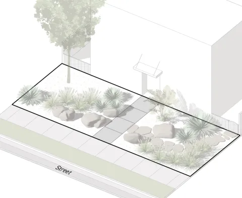
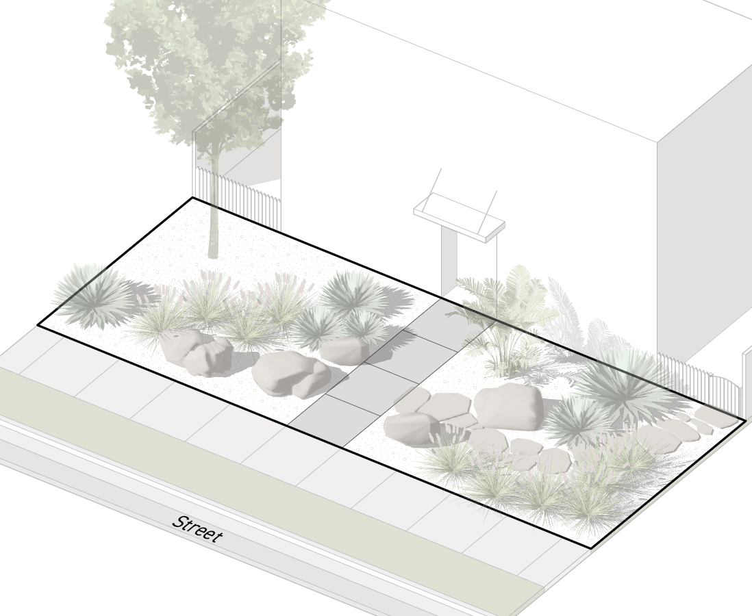
a.Type A1
Intended for frontage yards where buildings should engage directly with the public realm to provide visual interest and activation, especially where ground story uses are commercial or non-fenced frontage yards are predominant.
Dimensional Standards
For measurement see Sec. 3C.3.2.D.
Hedge height (max)
Prohibited
Fence/wall height (max)
Prohibited
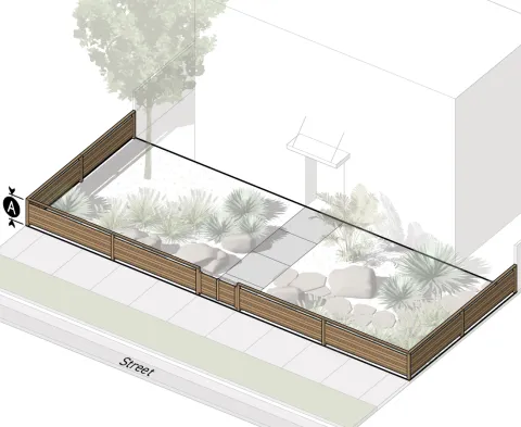
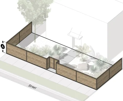
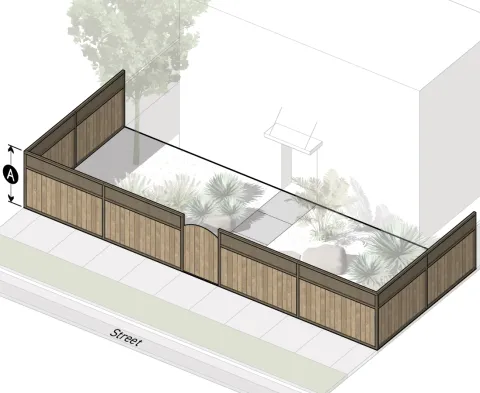
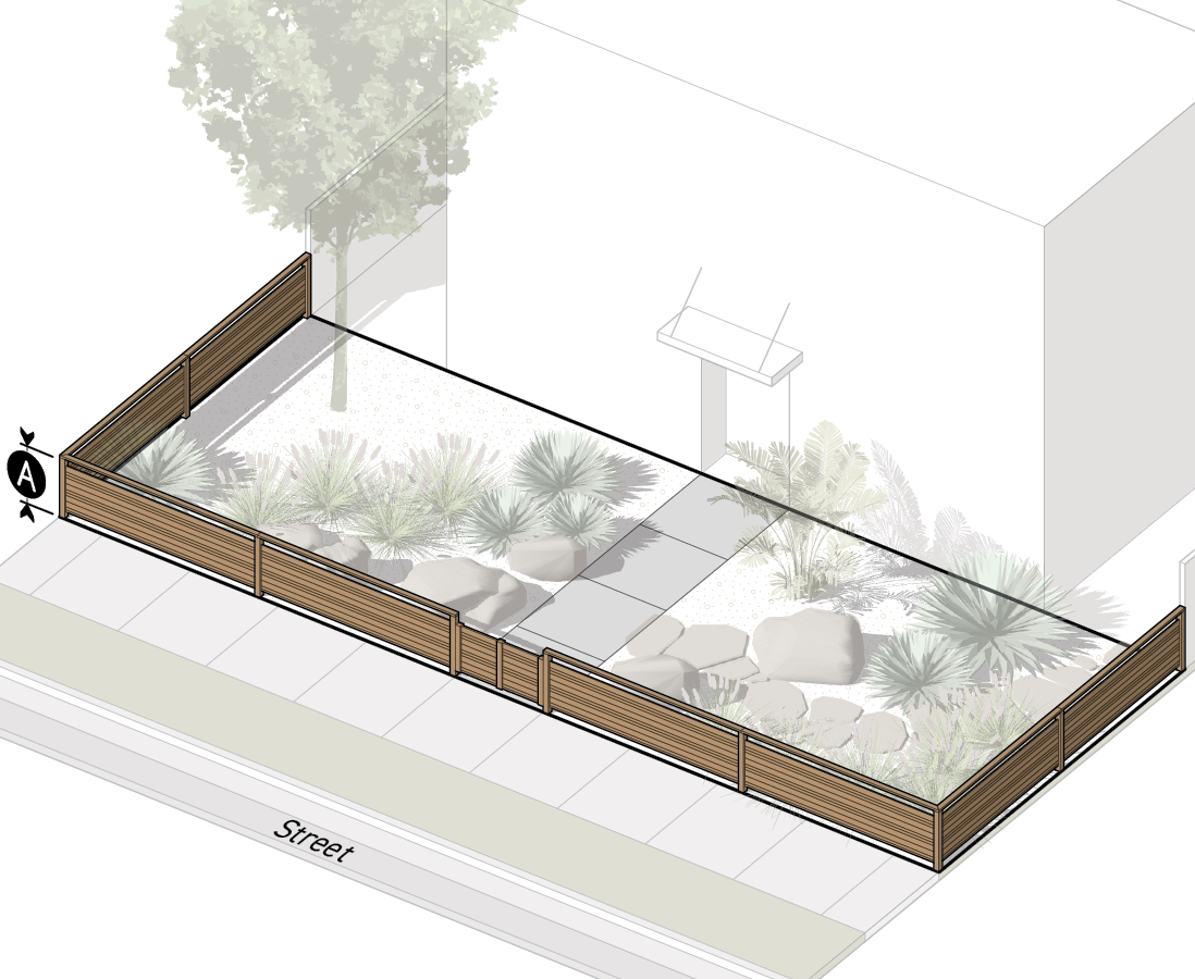
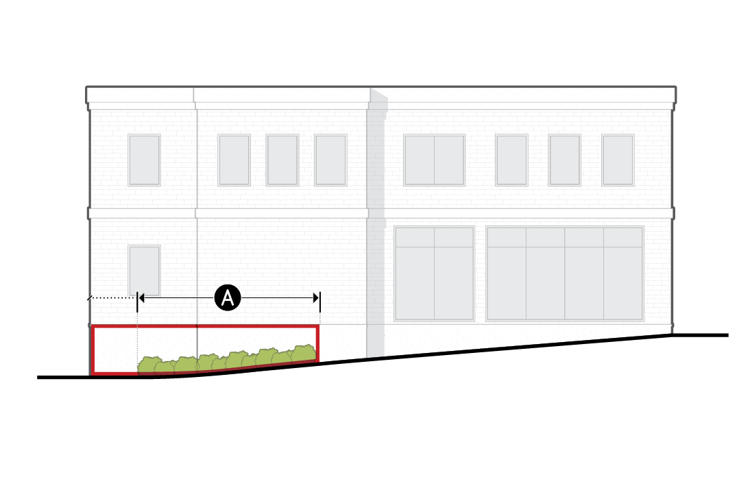
b.Type A2
Intended for frontage yards where the need for visual interest and activation along the public realm shall be balanced with the need for separation between private ground story uses and the public realm.
Dimensional Standards
For measurement see Sec. 3C.3.2.D.
Hedge height (max)
3.5'
A
Fence/wall height (max)
3.5'
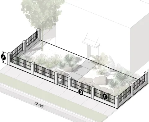
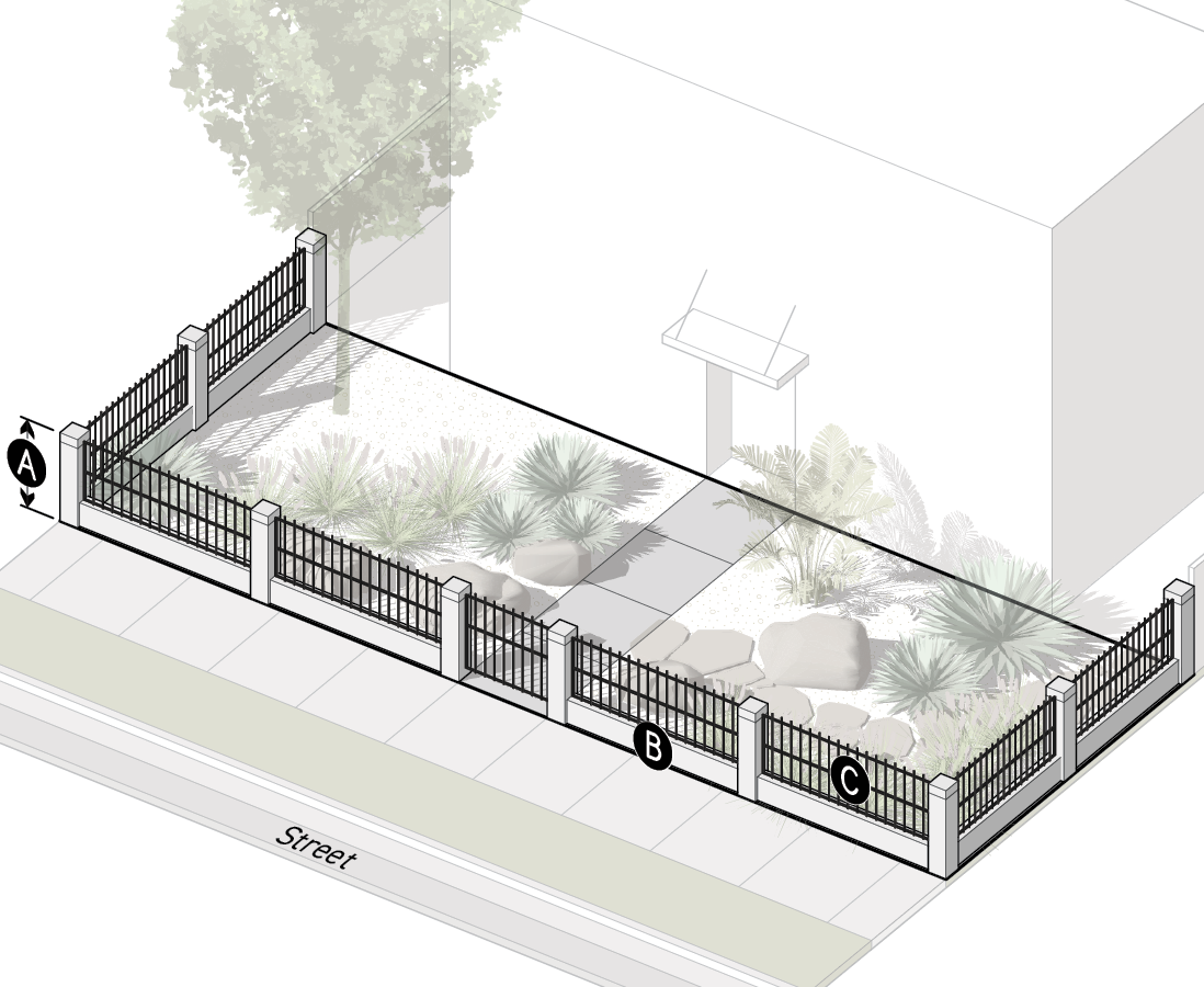
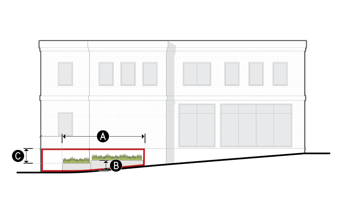
c.Type A3
Intended for frontage yards where the need for visual interest and activation along the public realm shall be balanced with the need for security between private ground story uses and the public realm.
Dimensional Standards
For measurement see Sec. 3C.3.2.D.
Hedge height (max)
3.5'
Fence/wall
A
Height (max)
6'
B
Opacity below 3.5' in height (max)
100%
C
Opacity 3.5' and above in height (max)
50%
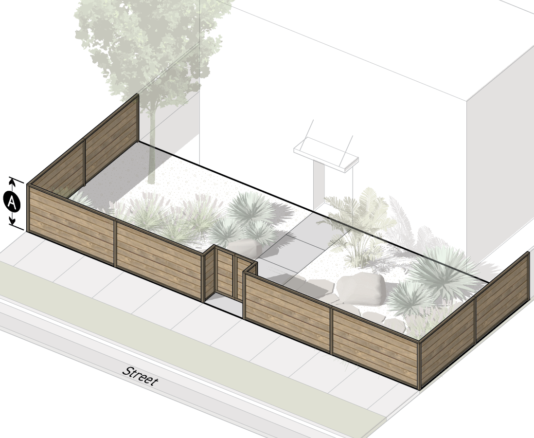
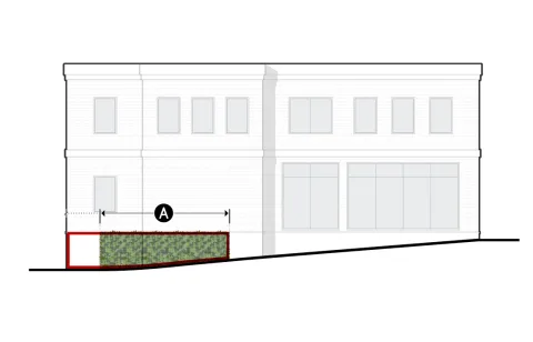
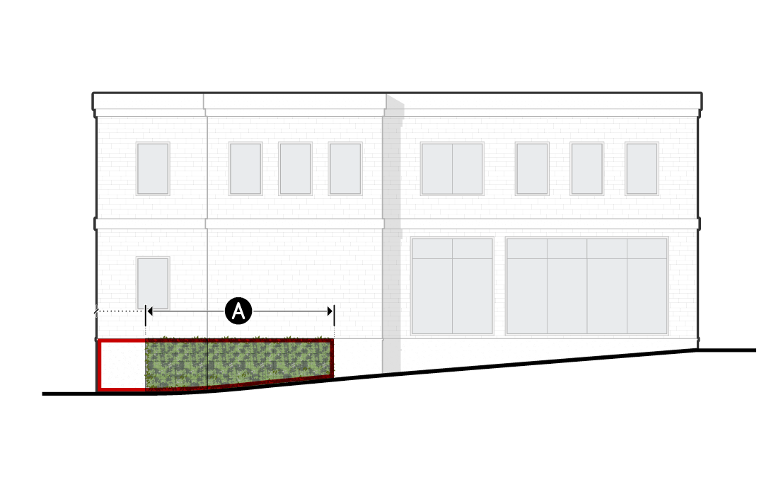
d.Type A4
Intended for frontage yards in areas with high pedestrian and automobile traffic, where visual interest and activation along the public realm is less critical than the need to mitigate impacts from the public realm on private ground story uses.
Dimensional Standards
For measurement see Sec. 3C.3.2.D.
Hedge height (max)
6'
A
Fence/wall height (max)
6'
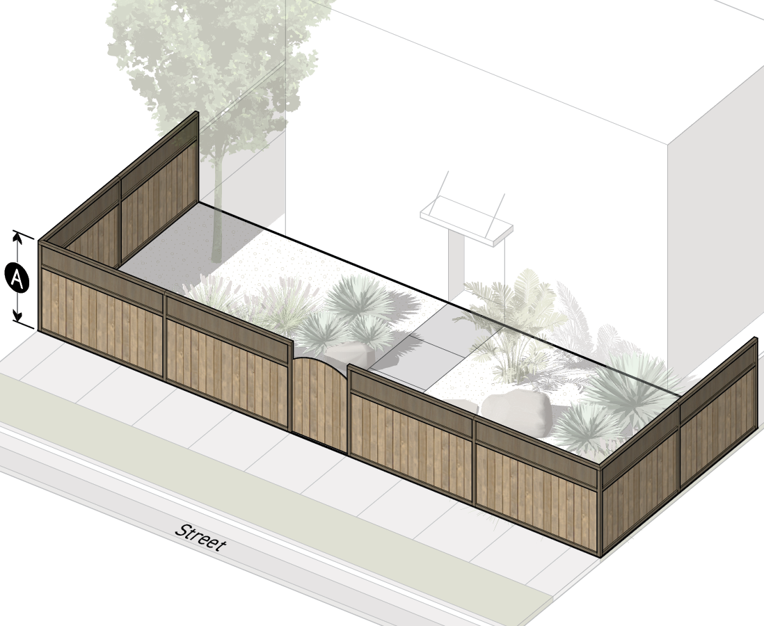
e.Type A5
Intended for frontage yards in areas with high pedestrian and automobile traffic, where visual interest and activation along the public realm is less critical than the need to mitigate intrusions from the public realm on private ground story uses.
Dimensional Standards
For measurement see Sec. 3C.3.2.D.
Hedge height (max)
8'
A
Fence/wall height (max)
8'
Measurement
Frontage Yard
For frontage yard designations and their measurement see Sec. 14.2.16. (Yards).
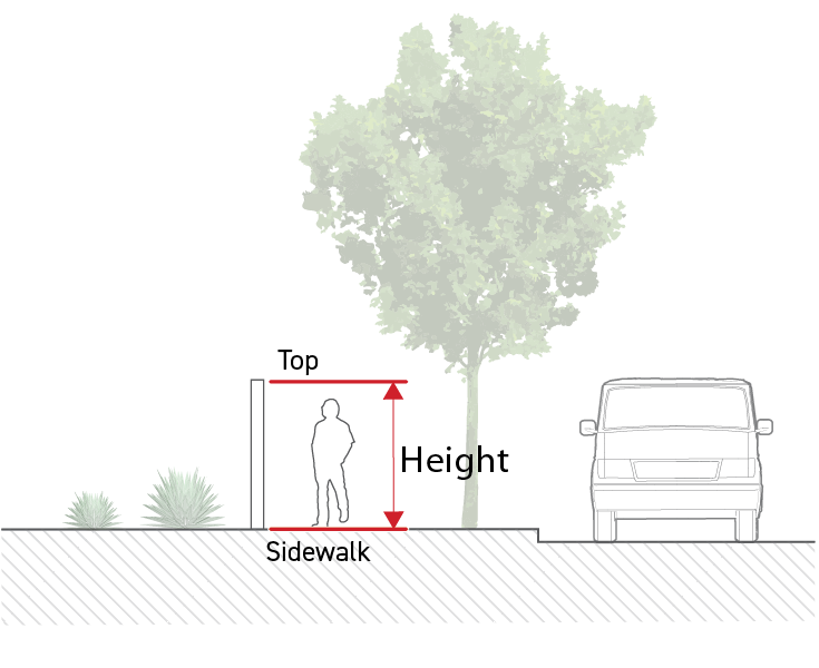
Fence & Wall Height
Where a public sidewalk is located within five feet of a wall or fence, height is measured vertically from the topmost point of the wall or fence to the adjacent public sidewalk.

Where no sidewalk exists within five feet of a wall or fence, height is measured vertically from the topmost point of the wall or fence to the finished grade at the base of the wall or fence on the side that faces outward from the lot.
To measure retaining walls see Sec. 4C.9.2. (Retaining Walls).
Fence/wall height maximums listed as "Prohibited" allow no fence or wall within the frontage yard.
Hedge Height
Hedge height is measured according to Sec. 4C.6.4.D.11. (Height at Maturity).
Hedge height maximums listed as "Prohibited" allow no hedge within the frontage yard.
Opacity
To measure opacity, see Sec. 14.2.13. (Opacity (%)).
Public Access Easement
For a lot with a public access easement, see Sec. 14.2.17.B.7. (Frontage Yard Fence & Wall).
Exceptions
Fences and walls located in a frontage yard may integrate outdoor lighting, entry arbors, and other accessory encroaching elements that exceed the maximum fence/wall height specified by the applicable frontage yard fence & wall type, provided all of the following are met:
The cumulative length of fence or wall that includes encroaching elements is no more than 10 percent of the total fence length located in the frontage yard,
No individual encroaching element may be wider than six feet, measured along the length of the fence or wall,
One encroaching element for each 40 feet of fence length may exceed the maximum fence and wall height by up to 40 inches. All other encroaching elements shall only exceed the maximum fence and wall height up to 18 inches.
Relief
A deviation up to 15 percent from any allowed frontage yard fence & wall type dimensional standard may be granted in accordance with Sec. 13B.5.2. (Adjustment).
A deviation from any allowed frontage yard fence & wall type standard may be granted as a variance in accordance with Sec. 13B.5.3. (Variance).
Div. 3C.4. Transparency
Sec. 3C.4.1. Transparent Area
Transparent area is defined as the amount of transparent area on a building facade.
Intent
The intent of the standards of this Section (Transparent Area) is to provide visual interest along the public realm by encouraging visual connections between the public realm and the interior of a building.
Applicability
Transparent area standards apply to the following project activities when "transparent area" is required by the applied Frontage District (Part 3B.): new construction, a major remodel, and an exterior modification. When the transparent area standards apply, the standards apply pursuant to Sec. 3A.2.2.B.3. (Frontage Applicable Facades) and Sec. 3A.2.2.B.4. (Frontage Applicable Building Depth).
Standards
Each applicable facade shall provide at least the minimum transparency specified by the applied Frontage District (Part 3B.).
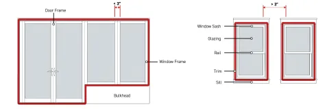
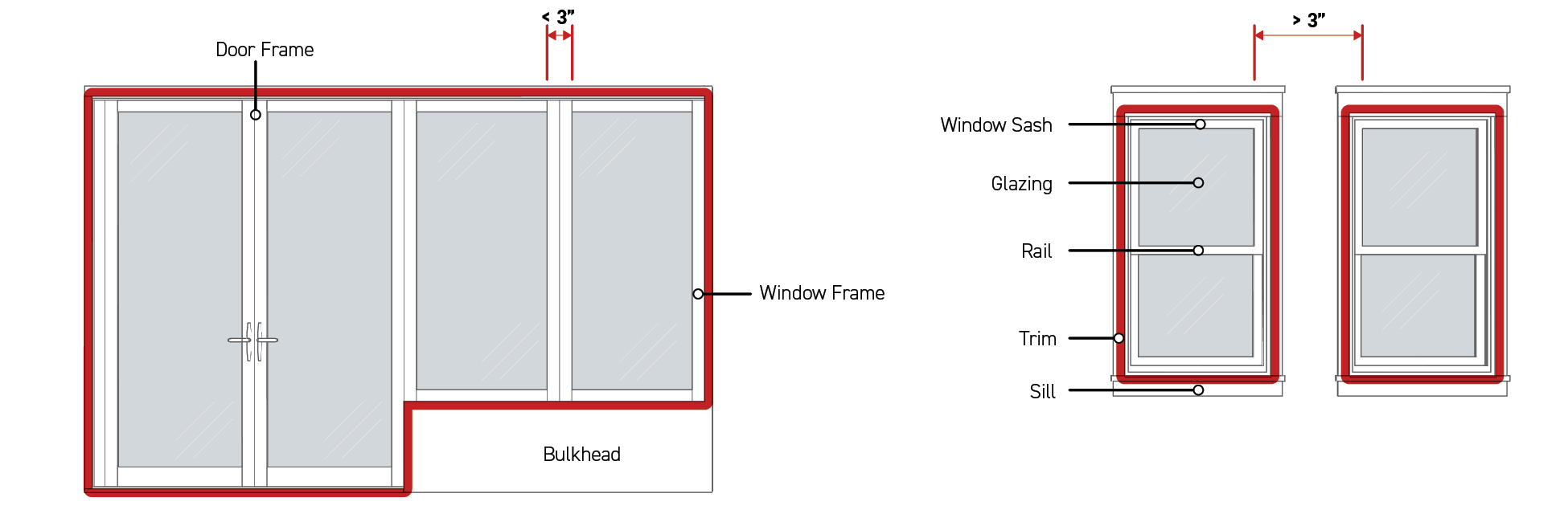
Window and door openings meeting the following requirements count toward transparent area:
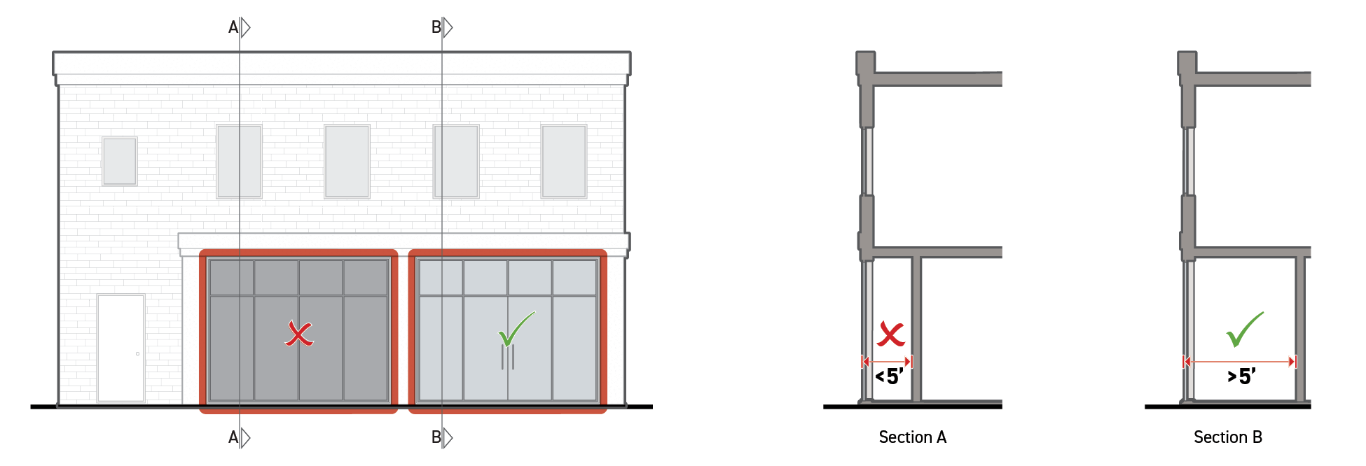
No walls, shelving, facade screens, or other interior or exterior visual obstructions shall be located within five feet of any ground story transparent area with the exception of visual obstructions allowed in subparagraph d below.
Exterior visual obstructions shall not be located within five feet of any upper story transparent area with the exception of visual obstructions allowed in subparagraph d below.
Visual obstructions may be located five feet or greater from a facade area counting toward transparent area.

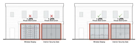
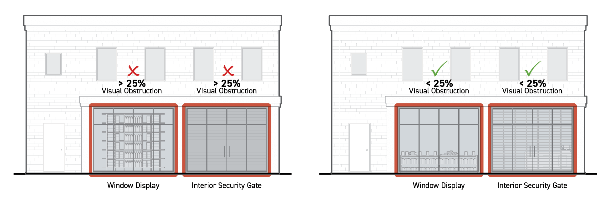
The following visual obstructions may be located less than five feet from facade area counting toward transparent area:
Windows obscured by interior security gates and window displays may count toward transparent area, provided no more than 25 percent of the transparent area of any individual window is visually obstructed for any individual window counting toward transparent area. For measuring visual obstruction, see Sec. 14.2.13. (Opacity (%)).
Windows obscured by fixed exterior facade screens may count toward transparent area, provided no more than 25 percent of the total transparent area is visually obstructed for any individual window opening counting toward transparent area. Percentage of visual obstruction is measured as opacity.
Transparent area covered by window signs may count toward transparent area provided the window signs are permitted by the applied Development Standards District (Part 4B.).
Areas of transparency may be made temporarily opaque by operable window treatments, such as curtains or blinds.
Distance from transparent area is measured perpendicular to the exterior face of the transparent area.
To be considered transparent, window and door glazing shall meet the following requirements:
Transparent Area Standards
Visible Light
TransmittanceExternal
ReflectanceGround story
More than 60%
Less than 20%
Upper stories
More than 30%
Less than 40%
Muntins, mullions, window sashes, window frames, and door frames, no more than three inches wide may be considered transparent area when contained within a window opening or door opening occupied by a window or glazed door assembly where all included glazing meets the transparent area requirements above.
Measurement
Ground Story
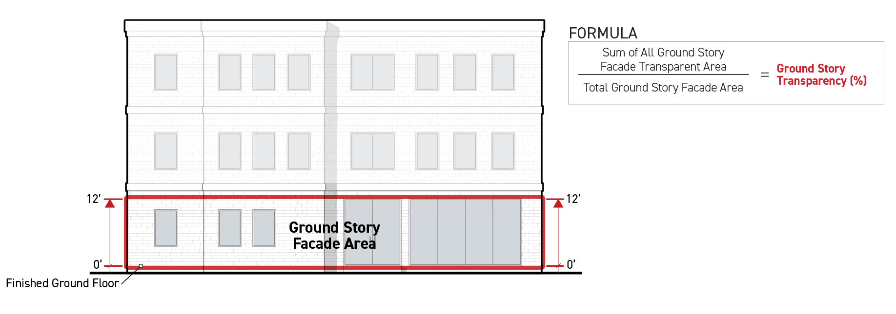
Ground story transparency is a percentage, calculated as the sum of all ground story facade area meeting the standards for transparent area divided by the total ground story facade area.
In calculating ground story transparency, ground story facade area is measured in the following ways:
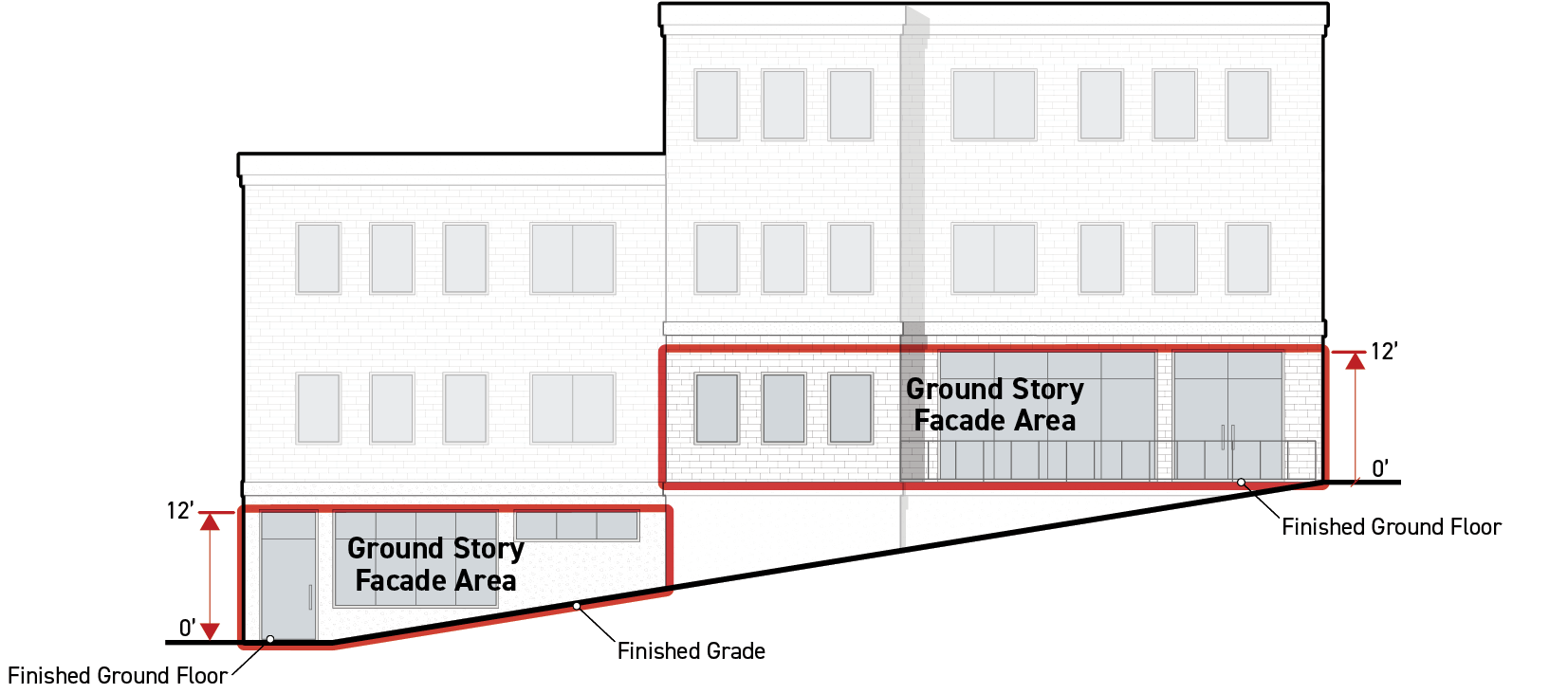
Ground story facade area is measured as the above-grade facade area between zero and 12 feet above the top of the finished floor of the ground story.

If the ground story height is less than 12 feet, the ground story facade area is measured as the total above-grade portion of a facade between the top of the finished floor of the ground story and the top of the finished floor above. When there is no story above, ground story height is measured to the top of the uppermost surface of the ceiling structure above.
No portion of a ground story located below finished grade is included in ground story facade area.

Upper Stories
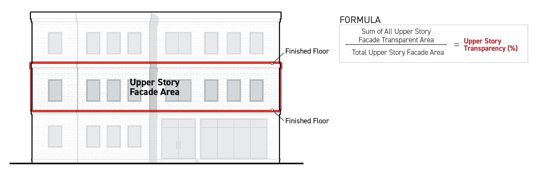
The facade area along each upper story shall meet the required transparency standard. .
Upper story transparency is a percentage, calculated as the sum of all upper story facade area meeting the standards for transparent area divided by the total upper story facade area for each story.
In calculating upper story transparency, the upper story facade area is measured as the portion of a facade area between the top of the finished floor for that story to the top of the finished floor above, regardless of story height. When there is no story above, it is measured to the top of the uppermost surface of the ceiling structure above.

Exceptions
Transparent area standards do not apply to portions of building facades that enclose a parking structure except where parking structures are required to be wrapped by the applied Development Standards District (Part 4B.).
Relief
Up to a 10 percent reduction from the total required transparent area may be granted in accordance with Sec. 13B.5.2. (Adjustment).
A deviation from required transparent area standards may be granted as a variance in accordance with Sec. 13B.5.3. (Variance).
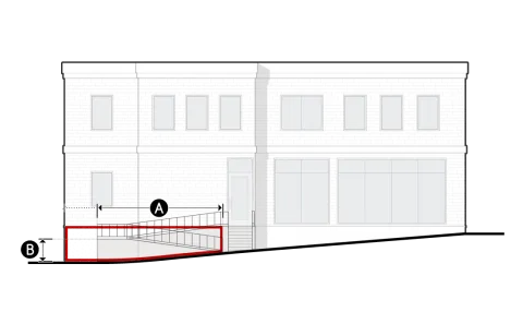
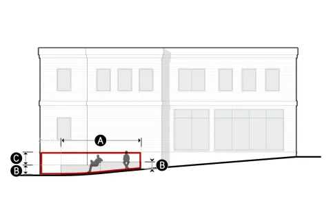
Sec. 3C.4.2. Active Wall Spacing
Active wall spacing is defined as the horizontal distance between widths of ground story facade and foundation wall with window or door openings.
Intent
The intent of the standards of this Section (Active Wall Spacing) is to provide visual interest and activation along the public realm by limiting areas without visual or physical connections between the public realm and the interior of a building.
Applicability
Active wall spacing standards apply to new construction, a major remodel, or an exterior modification.
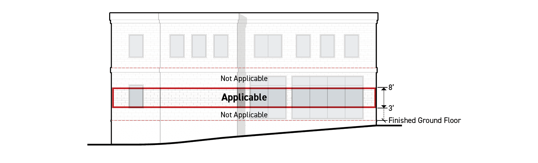
Active wall spacing standards apply to the following facades:
All portions of ground story frontage applicable facades pursuant to Sec. 3A.2.2.B.3. (Frontage Applicable Facades) located between three feet and eight feet from the ground floor elevation measured vertically.

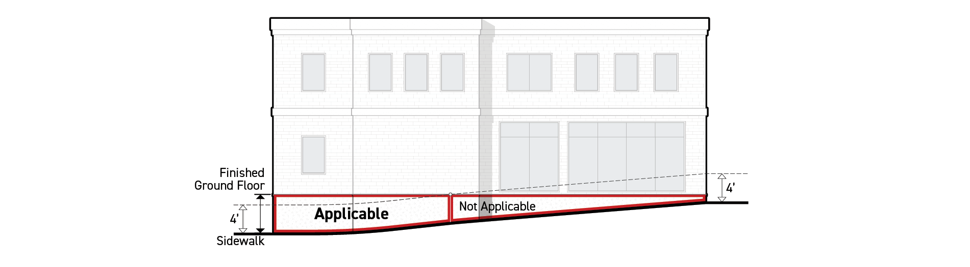
All portions of foundation walls on frontage applicable facades pursuant to Sec. 3A.2.2.B.3. (Frontage Applicable Facades) that are exposed four feet in height or greater above sidewalk grade. If foundation walls are set back more than 10 feet from a sidewalk, exposed height is measured from the lowest elevation of finished grade within five feet, measured from and perpendicular to the foundation wall.
Standards
Active Wall Spacing on Ground Story Facade
Window and door openings meeting Sec. 3C.4.1. (Transparent Area) on ground story facades shall be separated by a distance no greater than the maximum active wall spacing. For exceptions to this standard, see Subsection E. (Exceptions) below.
Active Wall Spacing on Foundation Wall
Applicable portions of foundation walls shall be no wider than the maximum active wall spacing specified by the applied Frontage District (Part 3B). For exceptions to this standard, see Subsection E. (Exceptions) below.
Measurement
Active Wall Spacing on Ground Story Facade
Active wall spacing is measured horizontally and parallel to the frontage lot line from edge of transparent area to edge of transparent area, and edge of transparent area to edge of ground story facade.

Active Wall Spacing on Foundation Wall
Active wall spacing is measured horizontally for any individual width of applicable foundation wall that does not include transparent area.

Exceptions
Inapplicable Facades
Active wall spacing standards do not apply to upper story facades.
Active wall spacing standards do not apply to portions of building facades enclosing a parking structure except where parking structures are required to be wrapped or fenestrated by the applied Development Standards District (Part 4B).
Inactive Wall Treatment Alternatives
Ground story facades that exceed the maximum allowed active wall spacing may apply one or more ground story inactive wall treatment alternatives to the applicable facade area between door or window openings and increase the active wall spacing by 50 percent per Paragraph 3. (Ground Story Inactive Wall Treatment Alternatives) below.
Facades designed with foundation walls that exceed the maximum allowed active wall spacing may apply one or more foundation inactive wall treatment alternatives to the facade area between active foundation walls and double the allowed active wall spacing per Paragraph 4. (Foundation Inactive Wall Treatment Alternatives) below.
Plants provided to meet the requirements of Paragraph 3. (Ground Story Inactive Wall Treatment Alternatives) and Paragraph 4. (Foundation Inactive Wall Treatment Alternatives) below shall also comply with Div. 4C.6. (Plants).
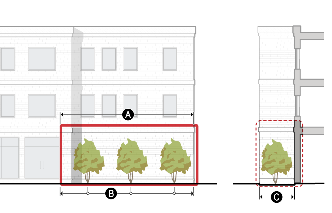
Ground Story Inactive Wall Treatment Alternatives
Permanent design improvements located between segments of ground story active wall and the public realm, designed to improve visual interest and the pedestrian experience.
a.Small Trees
Small trees planted between a ground story facade with no window or door openings and the public realm.
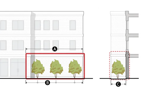
Dimensional Standards
For measurement see Sec. 3C.4.2.E.5.
A
Treatment width (min portion of inactive wall)
100%
Tree type
Small species
B
Planting frequency (min avg.)
5 per 100'
C
Planting area depth (min)
7'
See Div. 4C.6. (Plants) for additional standards.
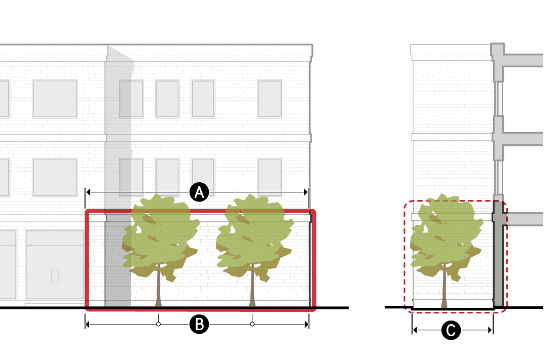
b.Large Trees
Large trees planted between a ground story facade with no window or door openings and the public realm.
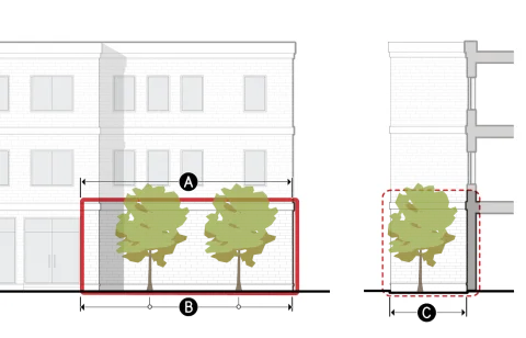
Dimensional Standards
For measurement see Sec. 3C.4.2.E.5.
A
Treatment width (min portion of inactive wall)
100%
Tree type
Large species
B
Planting frequency (min avg.)
3 per 100'
C
Planting area depth (min)
15'
See Div. 4C.6. (Plants) for additional standards.
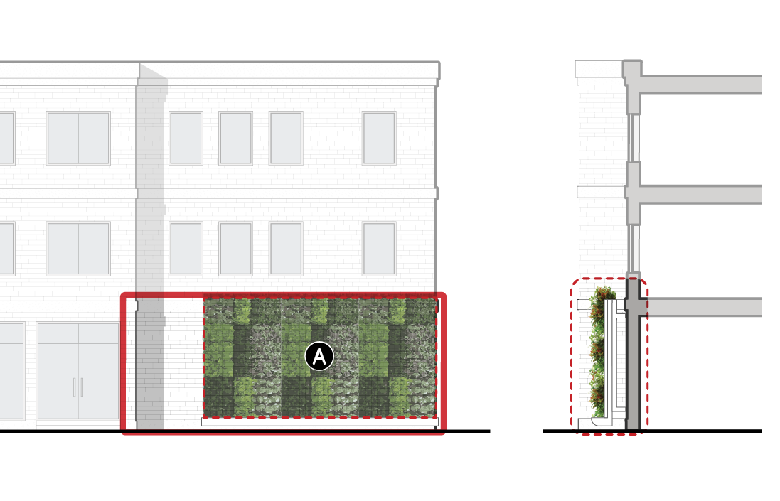
c.Living Wall
A permanently fixed assembly located between a ground story facade with no window or door openings and the public realm that supports plants, their growing medium, and irrigation.
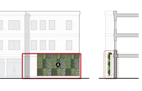
Dimensional Standards
For measurement see Sec. 3C.4.2.E.5.
A
Treatment area (min % of ground story facade with inactive walls)
75%
Planting area depth (min)
n/a
See Div. 4C.6. (Plants) for additional standards.
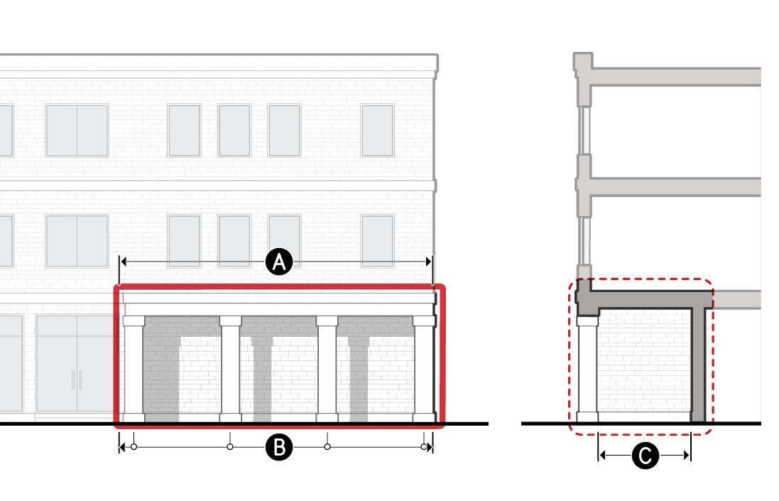
d.Colonnade
A sequence of columns located between a ground story facade with no window or door openings and the public realm, providing an exterior occupiable space along the inactive wall.
Dimensional Standards
For measurement see Sec. 3C.4.2.E.5.
A
Treatment width (min portion of inactive wall)
100%
B
Column frequency (min avg.)
1 per 20'
C
Clear depth (min)
6'
Enclosure (max)
60%
Foundation Inactive Wall Treatment Alternatives
Permanent design improvements located between exposed foundation walls and the public realm, designed to improve visual interest and the pedestrian experience.
a.Foundation Planting
Screening plants located between a foundation wall with no window or door openings and the public realm.
Dimensional Standards
For measurement see Sec. 3C.4.2.E.5.
A
Treatment width (min portion of inactive wall)
75%
Plant type
Screening Plant
Planting frequency (min avg.)
3 per 10'
Planting area depth (min)
3'
See Div. 4C.6. (Plants) for additional standards.
b.Planter
Permanent structure containing plants and their growing medium located between a foundation wall with no window or door openings and the public realm.
Dimensional Standards
For measurement see Sec. 3C.4.2.E.5.
A
Treatment width (min)
75%
Plant coverage (min)
75%
Planting area depth (min)
2.5'
B
Height above sidewalk (max)
4'
C
Foundation wall reveal (max)
2'
See Div. 4C.6. (Plants) for additional standards.
c.Green wall
A structure permanently attached to a foundation wall with no window or door openings that supports climbing plants.
Dimensional Standards
For measurement see Sec. 3C.4.2.E.5.
A
Treatment area (min)
75%
Planting area depth (min)
1.5'
See Div. 4C.6. (Plants) for additional standards.
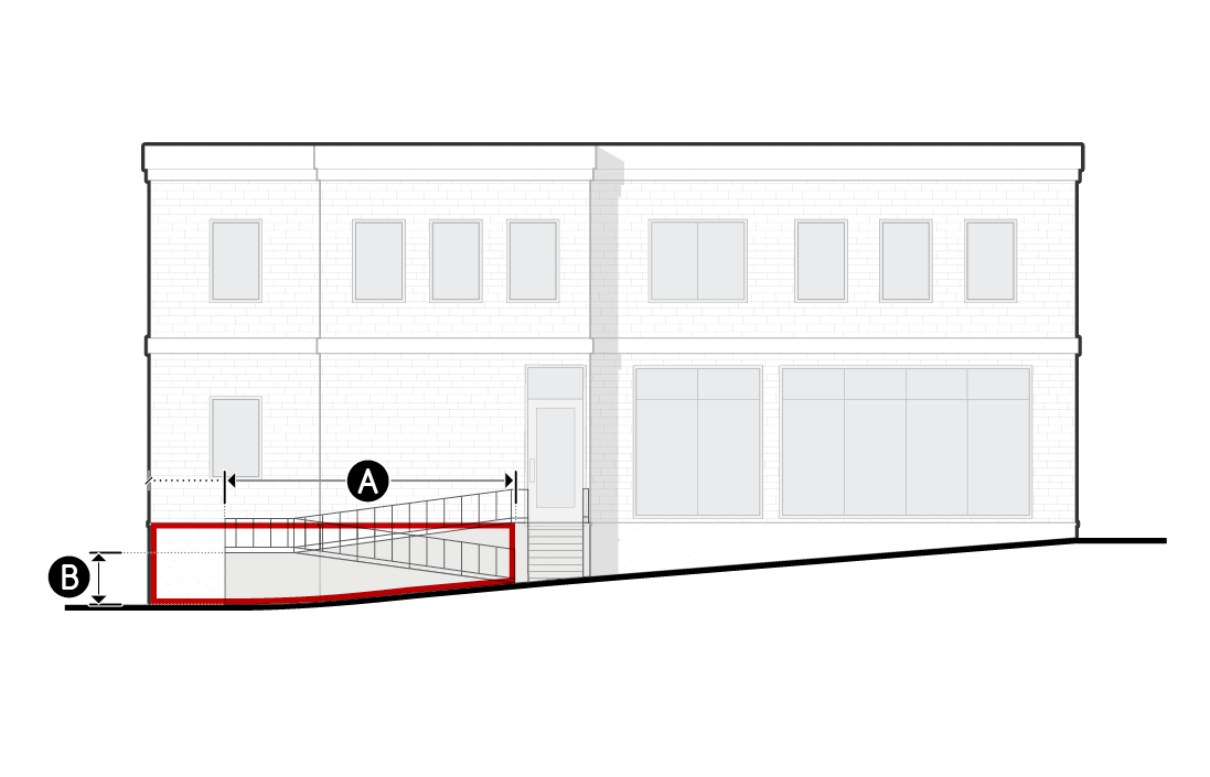
d.Pedestrian Access
Stairs or ramps providing pedestrian access to a street-facing entrance located between a foundation wall with no window or door openings and the public realm.
Dimensional Standards
For measurement see Sec. 3C.4.2.E.5.
A
Treatment width (min)
75%
B
Height above sidewalk (max)
4'
Additional access standards
See Div. 4C.1. (Pedestrian Access) for additional standards.
e.Seating
A permanent structure designed and intended for public seating located between a foundation wall with no window or door openings and the public realm.
Dimensional Standards
For measurement see Sec. 3C.4.2.E.5.
A
Treatment width (min)
75%
B
Height above sidewalk (min/max)
1.5'/3'
C
Foundation wall reveal (max)
3'
Seat depth (min)
2'
Inactive Wall Treatment Measurement
Treatment Width
Minimum treatment width percentage is calculated as the cumulative width of the provided inactive wall treatments divided by the total width of the provided active wall spacing.
Treatment Area
Minimum treatment area percentage is calculated as the cumulative area of the provided inactive wall treatments divided by the total applicable facade area within the provided active wall spacing.
Tree type
Tree type is measured as small or large species according to Sec. 4C.6.4.C.3.a.ii. (Tree Types).
Plant type
Plant type is measured as screening plants, groundcover, and turf plants, hedges, living walls, or climbing plants according to Sec. 4C.6.4. (Plant Design & Installation).
Plant Coverage
Minimum plant coverage is measured according to Sec. 4C.6.4.D.2. (Plant Coverage).
Planting Frequency
Planting frequency is a ratio of the minimum number of plants required over a specified width of active wall spacing. A minimum of one plant of the required plant type shall be provided regardless of the width of inactive wall treatment.
Column Frequency
Minimum column frequency is a ratio of the minimum number of columns required over a specified width of treated inactive wall treatment. A minimum of two columns shall be provided regardless of the inactive wall treatment width.
Planting Area Depth
Minimum planting area depth is measured as the horizontal dimension of growing medium at the narrowest point, measured perpendicular to the applicable street lot line. The planting area shall be open to the sky for at least the required planting area depth.
Clear Depth
Minimum clear depth is measured as the horizontal dimension of the occupiable portion of an architectural element at the narrowest point.
Height Above Sidewalk
Height above sidewalk is measured vertically from adjacent sidewalk grade to the topmost point of the inactive wall treatment.
For foundation walls located more than 10 feet from a sidewalk, maximum height above sidewalk is measured from the lowest elevation of finished grade within five feet, measured from and perpendicular to the foundation wall, to the topmost point of the inactive wall treatment.
Foundation Wall Reveal
Foundation wall reveal is measured vertically from the top of an inactive wall treatment to the ground floor elevation along the entire treated portion of an inactive foundation wall.
Seat Depth
Minimum seat depth is measured as the narrowest horizontal dimension of the area designed for public seating.
Enclosure
Maximum enclosure is measured according to Sec. 14.2.4. (Enclosure).
Relief
Deviation from inactive wall treatment standards may be granted in accordance with Sec. 13B.5.1. (Alternative Compliance).
An increase in allowed active wall spacing up to 20 percent may be granted in accordance with Sec. 13B.5.2. (Adjustment).
An increase in allowed active wall spacing and inactive wall treatment standards may be granted as a variance in accordance with Sec. 13B.5.3. (Variance).


Div. 3C.5. Entrances
Sec. 3C.5.1. Street-Facing Entrance
Street-facing entrance is defined as a door providing access from the public realm to the interior of a building.
Intent
The intent of the standards of this Section (Street-Facing Entrance) is to provide visual interest along the public realm, orient buildings to the public realm, and promote greater use and activation of the public sidewalk by limiting the width of frontage without physical connections between the public realm and the interior of a building.
Applicability
Street-facing entrance standards apply to new construction, a major remodel, or an exterior modification. When the street-facing entrance standards apply, the standards apply to those portions of buildings and structures where frontage standards apply pursuant to Sec. 3A.2.2.B. (Applicable Components of Lots, Buildings, & Structures).
Standards
General
Where a street-facing entrance is required by the applied Frontage District, street-facing entrances shall be provided at a rate based on the maximum entrance spacing specified in the applied Frontage District. A minimum of one street-facing entrance shall always be provided.
To qualify as a street-facing entrance, building entrances shall meet the following standards:
Be located on the ground story facade.
Provide both ingress and egress pedestrian access to the ground story of the building.
Remain operable at all times. Access may be controlled and limited to residents or tenants.
Provide no access directly to motor vehicle use areas, utility areas or fire stairs.
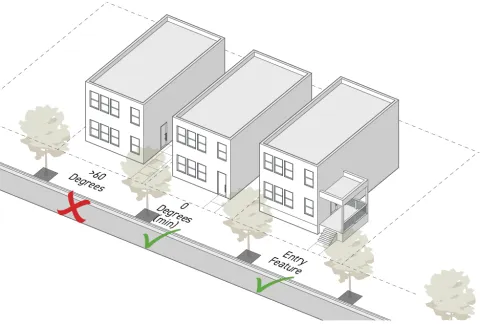
The exterior door surface shall be angled between zero to 60 degrees, measured parallel to the frontage lot line or the door shall have direct access from an entry feature allowed by the applied Frontage District (Part 3B.) having a pedestrian access point which faces the frontage lot line.
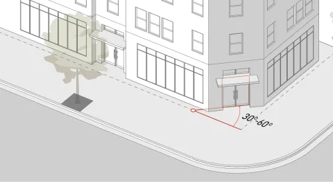
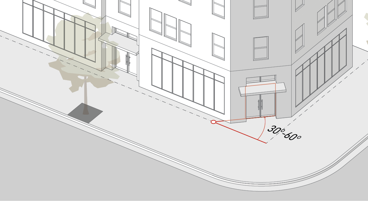
On a corner lot or a lot with a Dual Frontage District (Div. 3B.8.) applied, having intersecting frontage lot lines, an entrance facing both intersecting frontage lot lines and angled between 30 to 60 degrees, measured parallel to each of those frontage lot lines, may be used to meet the requirement for a street-facing entrance along both frontages.
Non-required entrances are allowed in addition to required entrances.
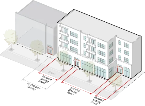
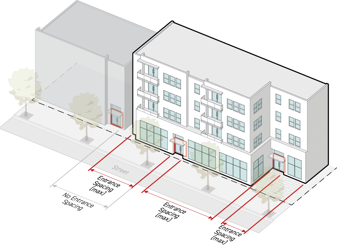
Entrance Spacing
The distance between street-facing entrances meeting the standards of Sec. 3C.5.1.C. (Standards).
Measurement
The minimum number of street-facing entrances required for each frontage applicable facade is the frontage-applicable facade width divided by the maximum entry spacing requirement.
Maximum entrance spacing is the greatest horizontal distance from edge of door to edge of door, and edge of door to edge of building, measured parallel to the frontage lot line.
Standards
Street-facing entrances shall not be separated by a distance greater than the maximum allowed entrance spacing.
The maximum entrance spacing requirements shall be met for each building individually, but are not applicable to adjacent or abutting buildings.
When the applied Frontage District (Part 3B.) specifies that a street-facing entrance is 'not required' but does specify a maximum entrance spacing, a street-facing entrance shall only be required if the building width along the indicated frontage lot line is greater than the specified entrance spacing. Street-facing entrances shall then be required in accordance with the maximum entrance spacing requirement specified.
Measurement
Street-facing entrance is measured as "provided" or "not provided" based on the presence of entrances meeting Sec. 3C.5.1.C. (Standards).
Relief
Deviation from street-facing entrance standards may be granted in accordance with Sec. 13B.5.1. (Alternative Compliance).
An increase in entrance spacing up to 20 percent may be granted in accordance with Sec. 13B.5.2. (Adjustment).
Deviation from street-facing entrance and entrance spacing standards may be granted as a variance in accordance with Sec. 13B.5.3. (Variance).
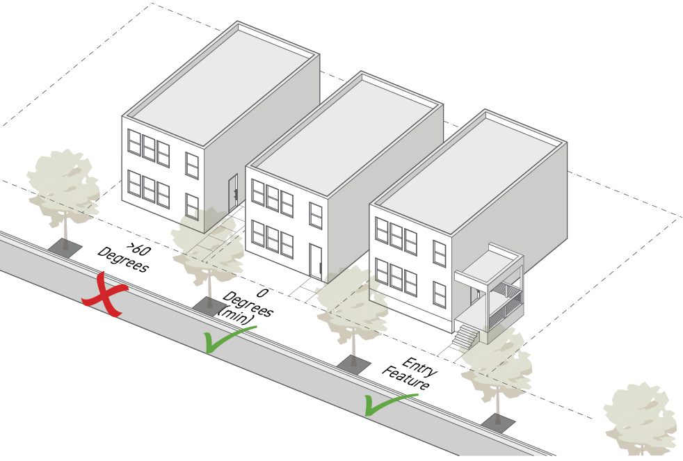
Sec. 3C.5.2. Entry Feature
Entry features are improved design standards applied to each entrance along the public realm.
Intent
The intent of the standards of this Section (Entry Feature) is to provide architectural embellishment of entrances that promote inconspicuous wayfinding in the public realm, provide greater shelter and comfort to users, promote visual interest along the public realm, and highlight the connection between the public and private realm to improve walkability.
Applicability
Entry feature standards apply to all required street-facing entrances where entry features are required by the applied Frontage District (Part 3B.).
Standards
General
Each required street-facing entrance shall include an entry feature that meet the standards for one of the allowed entry feature options specified by the applied Frontage District (Part 3B.).
Required entry features shall abut and provide direct access to a street-facing entrance.
Required entry features shall provide direct access from the public realm associated with the frontage lot line.
For building setback encroachment regulations, see Sec. 2C.2.2.E. (Exceptions).
For encroachments into the public right-of-way, see Chapter IX. (Building Regulations), Sec. 91.32 (Encroachments into the Public Right-of-Way) of this Code.
In complying with entry feature standards, outdoor spaces such as landings and yards required by an entry feature count as occupiable space.
Entry Feature Options
Packages of design standards applied to each entrance along the public realm.
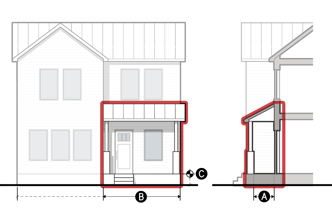
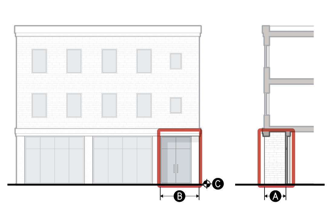
a.Porch
A wide, raised platform, projecting in front of a street-facing entrance, that is entirely covered but not enclosed.
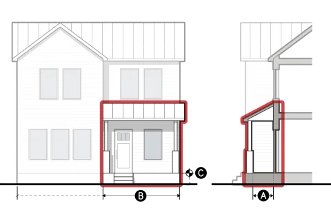
Dimensional Standards
For measurement see Sec. 3C.5.2.D.
A
Clear depth (min)
4.5'
B
Clear width (min)
12'
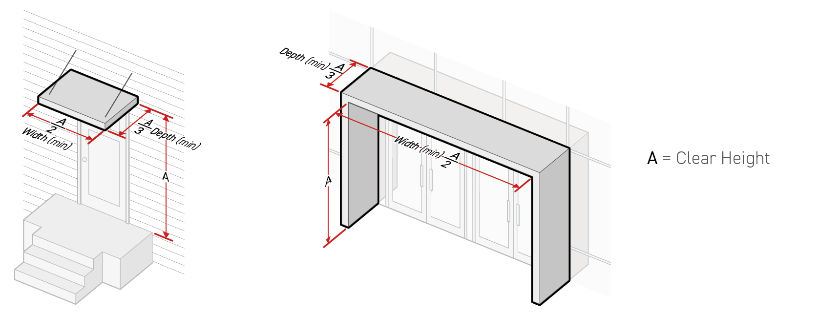
Clear height (min)
7.5'
Covered area (min)
100%
C
Finished floor elevation (min/max)
2'/5'
Enclosure (max)
50%
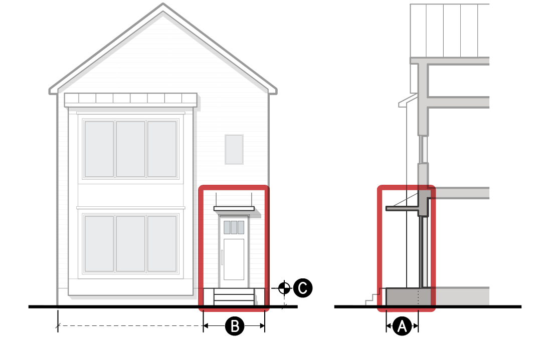
b.Raised Entry
A raised platform accessed from an exterior staircase, providing covered access to a street-facing entrance.
Dimensional Standards
For measurement see Sec. 3C.5.2.D.
A
Clear depth (min)
3'
B
Clear width (min)
4'
Clear height (min)
7.5'
Covered entrance
Required
C
Finished floor elevation (min/max)
2'/5'
Enclosure (max)
50%
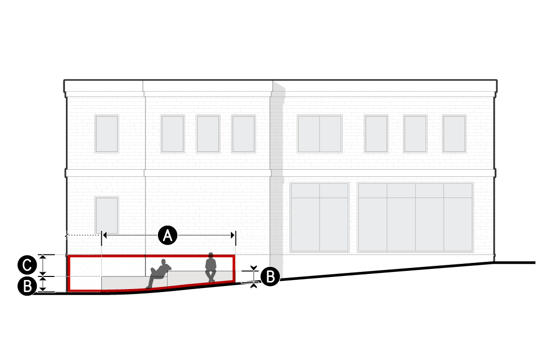
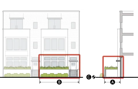
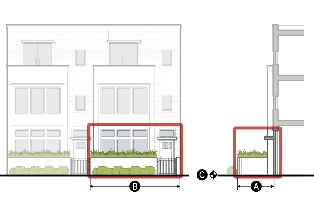
c.Forecourt
A yard screened with a short wall, fence or hedge that provides significant privacy for tenants located on the ground story, near sidewalk grade.
Dimensional Standards
For measurement see Sec. 3C.5.2.D.
A
Clear depth (min)
8'
B
Clear width (min)
10'
Clear height (min)
Open to sky
Covered entrance
Required
C
Finished floor elevation (min/max)
-2'/2'
Fence or wall height (min/max)
2.5'/4'
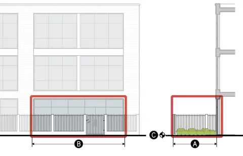
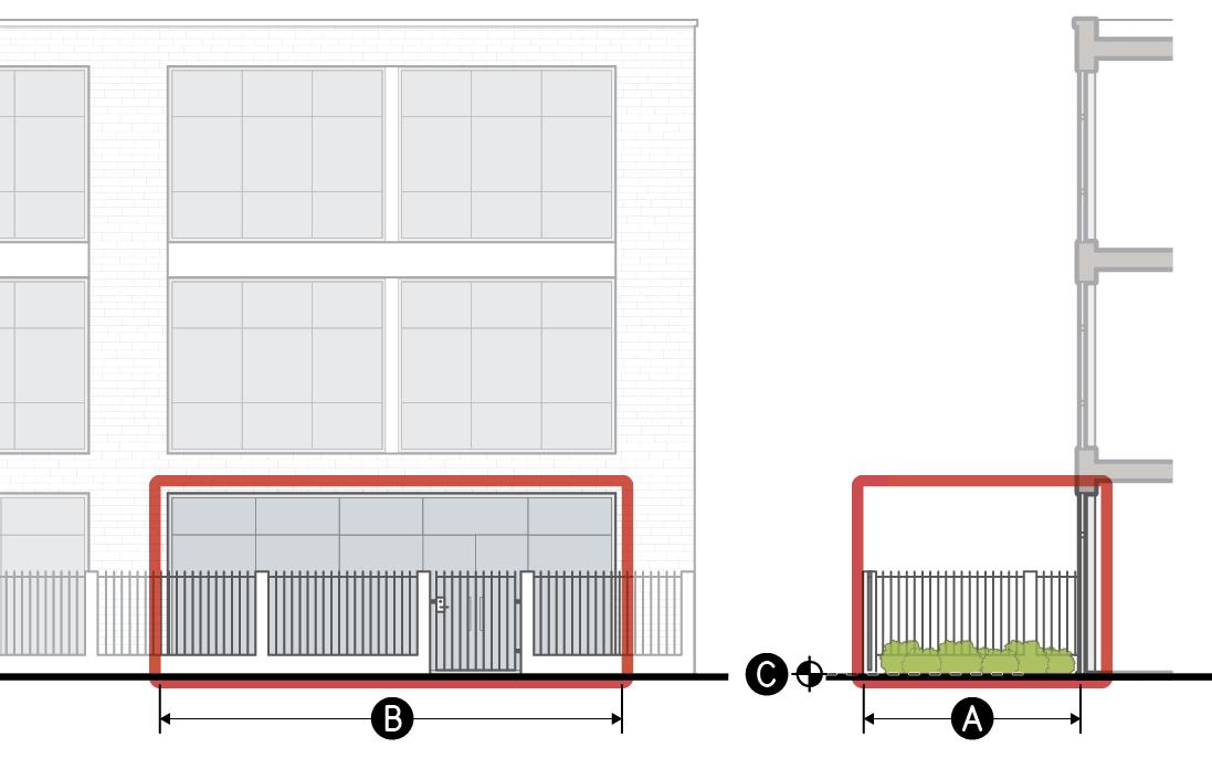
d.River Yard
A yard located between a building and a river trail with direct pedestrian access from inside the building to the river trail.
Dimensional Standards
For measurement see Sec. 3C.5.2.D.
A
Clear depth (min)
15'
B
Clear width (min)
15'
Clear height (min)
Open to sky
C
Finished floor elevation (min/max)
-2'/2'
Fence or wall height (max)
6'
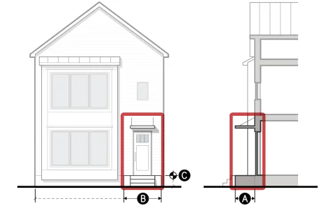
e.Recessed Entry
A space set behind the building face plane providing sheltered access to a street-facing entrance.
Dimensional Standards
For measurement see Sec. 3C.5.2.D.
A
Clear depth (min)
3'/15'
B
Clear width (min)
5'
Clear height (min)
7.5'
Covered entrance
Required
C
Finished floor elevation (min/max)
-2'/2'
Enclosure (max)
75%
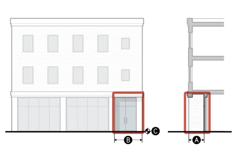
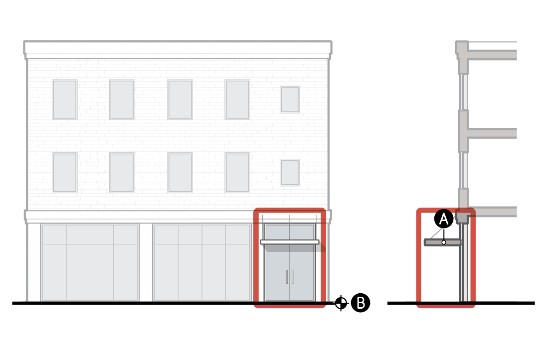
f.Covered Entry
A space that provides sheltered access to an at-grade street-facing entrance with an overhead projecting structure.
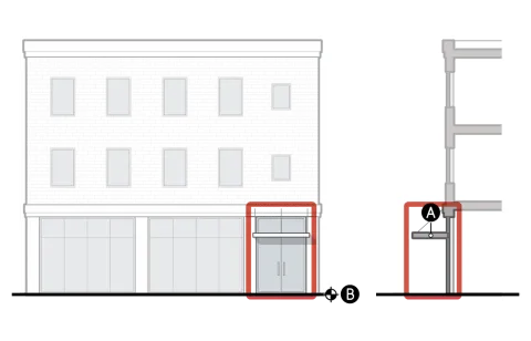
Dimensional Standards
For measurement see Sec. 3C.5.2.D.
Clear height (min)
7.5'
A
Covered entrance
Required
B
Finished floor elevation (min/max)
-2'/2'
Enclosure (max)
50%
For encroachments into the public right-of-way, see Chapter IX. (Building Regulations), Sec. 91.32. (Encroachments into the Public Right-of-Way) of this Code.
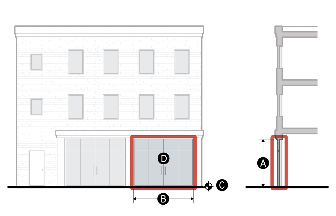
g.Storefront Bay
A facade area with a high level of contiguous transparency accentuating an at-grade street-facing entrance.
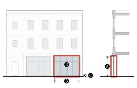
Dimensional Standards
For measurement see Sec. 3C.5.2.D.
A
Transparent area height (min)
9'
B
Transparent area width (min)
8'
Covered entrance
Required
C
Finished floor elevation (min/max)
-2'/2'
D
Transparency (min)
90%
Fence or wall height (max)
0'
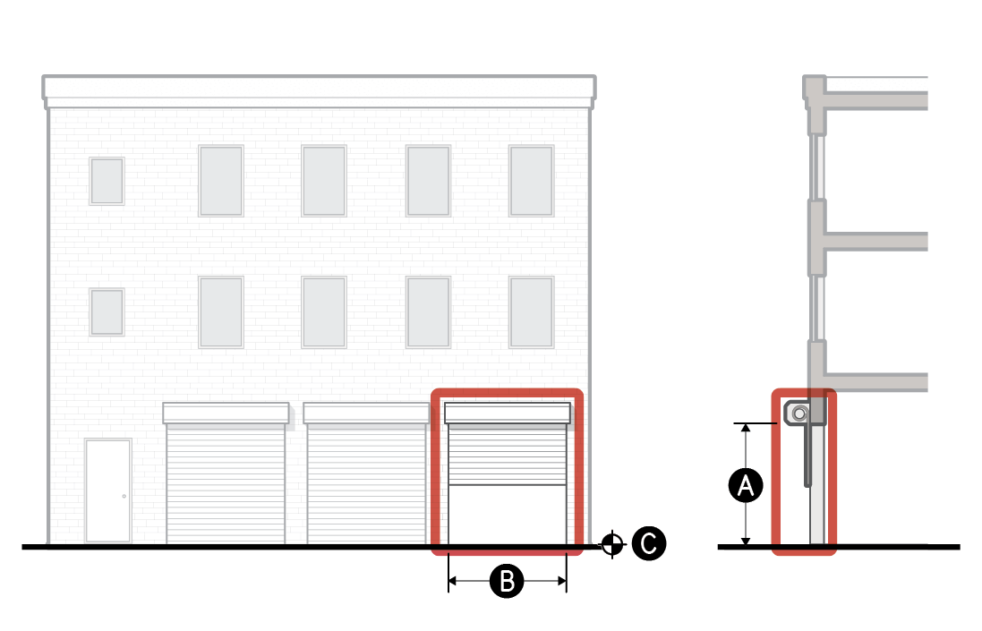
h.Market Stall
A facade area equipped with an overhead door or operable facade that is open to the public realm during hours of operation.
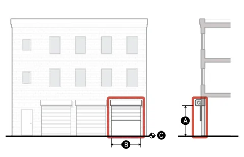
Dimensional Standards
For measurement see Sec. 3C.5.2.D.
Clear depth (min)
10'
A
Clear height (min)
9'
B
Clear width (min)
6'
C
Finished floor elevation (min/max)
-2'/5'
Fence or wall height (max)
0'
A market stall does not count toward transparency unless it meets the standards for transparent area when shut.
Measurement
General
Entry feature is measured as "provided" or "not provided" for each required street-facing entrance based on whether the design of a street-facing entrance meets the standards of an allowed entry feature specified by the applied Frontage District (Part 3B.).
In complying with entry feature standards, outdoor spaces such as landings and yards required by an entry feature count as occupiable space.
Clear Depth
Clear depth is measured as the shallowest horizontal dimension of the occupiable space immediately abutting or surrounding each required street-facing entrance, measured perpendicular to the applicable building facade to the interior of the occupiable space.
Clear Width
Clear width is measured as the narrowest horizontal dimension of the occupiable space immediately abutting or surrounding each required street-facing entrance, measured parallel to the applicable street lot line.
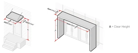
Clear Height
Clear height is measured vertically at the shortest point between the finished floor elevation or the finished grade of the occupiable space immediately abutting or surrounding each required street-facing entrance to the bottom of the surface of any solid overhead structure creating covered space within the occupiable space.
Where a minimum clear height is specified as 'open to sky', the occupiable space immediately abutting each required street-facing entrance shall be uncovered.
Covered Entrance
When required as part of an entry feature, a canopy, roof or other sheltering structure, the covered entrance shall cover the occupiable exterior area immediately abutting the associated street-facing entrance.
The minimum depth of the covered area shall be the clear height of the covered area divided by three.
The minimum width of the covered area shall be the clear height of the covered area divided by two.
Covered Area
Covered area is measured as the occupiable space of an entry feature that is covered by a canopy, roof or other sheltering structure, divided by the total occupiable entry feature area.
Finished Floor Elevation
Finished floor elevation is measured from the average sidewalk grade along the adjacent sidewalk to the top of the finished floor surface or ground surface of the entry feature. Where no sidewalk exists within 10 feet of the entry feature, finished floor elevation is measured perpendicular from the average finished grade within five feet of the entry feature, to the entry feature area.
Transparency
Transparency is the percentage of area meeting the transparent area standards of Sec. 3C.4.1.C. (Standards) provided for each street-facing entrance, divided by the required transparent area.
Required transparent area is calculated by multiplying the specified transparent area height by transparent area width. For the measurement of ground story transparency, see Sec. 3C.4.1.D.1. (Ground Story).
Transparent Area Height
Transparent area height is measured vertically from the top of the finished floor of the ground story to the shortest height of the transparent area provided.
Transparent Area Width
Transparent area width is measured horizontally from the outer edges of the transparent area provided along the narrowest width.
Enclosure
For the measurement of enclosure, see Sec. 14.2.4. (Enclosure).
Fence or Wall Height
Fence or wall height is measured according to Sec. 3C.3.2.D.2. (Fence & Wall Height).
Relief
A deviation from entry feature dimensional standard up to 15 percent may be granted in accordance with Sec. 13B.5.2. (Adjustment).
Deviation from any entry feature standard may be granted as a variance in accordance with Sec. 13B.5.3. (Variance).
Div. 3C.6. Ground Story
Sec. 3C.6.1. Ground Story Height
Ground story height is defined as the floor-to-floor height of the story of a building having its finished floor elevation nearest to the finished grade.
Intent
The intent of the standards of this Section (Ground Story Height) is to promote active uses that are directly connected to the public realm, and ensure high-quality ground story spaces that are adaptable and appropriate to their context.
Applicability
Ground story height standards apply to new construction. When the ground story height standards apply, the standards apply to all portions of the ground story, within the first 15 feet of a facade of a new building or structure, pursuant to Sec. 3A.2.2.B.3. (Frontage Applicable Facades).
Standards
All occupiable space located in applicable portions of the ground story shall have floor-to-floor height of no less than the ground story height minimum.
Measurement
Ground story height is measured vertically from the top of the finished ground story to the top of the finished floor above.
Where no story exists above, ground story height is the shortest vertical distance from the top of the ground floor elevation to the top of the ceiling or roof structure above.
For determining the ground story, see Sec. 14.2.10.A. (Ground Story).
Relief
A reduction in required ground story height up to one foot may be granted in accordance with Sec. 13B.5.2. (Adjustment).
Deviation from ground story height standards may be granted as a variance in accordance with Sec. 13B.5.3. (Variance).
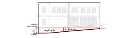
Sec. 3C.6.2. Ground Floor Elevation
Ground floor elevation is defined as the finished floor height associated with the story of a building having its finished floor elevation nearest to the finished grade.
Intent
The intent of the standards of this Section (Ground Floor Elevation) is to promote high-quality ground story spaces with direct connection and visual interplay with the public realm.
Applicability
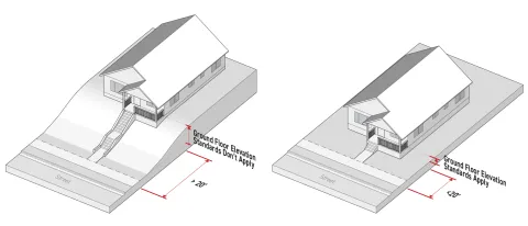
Ground floor elevation standards apply to new construction subject to the following:
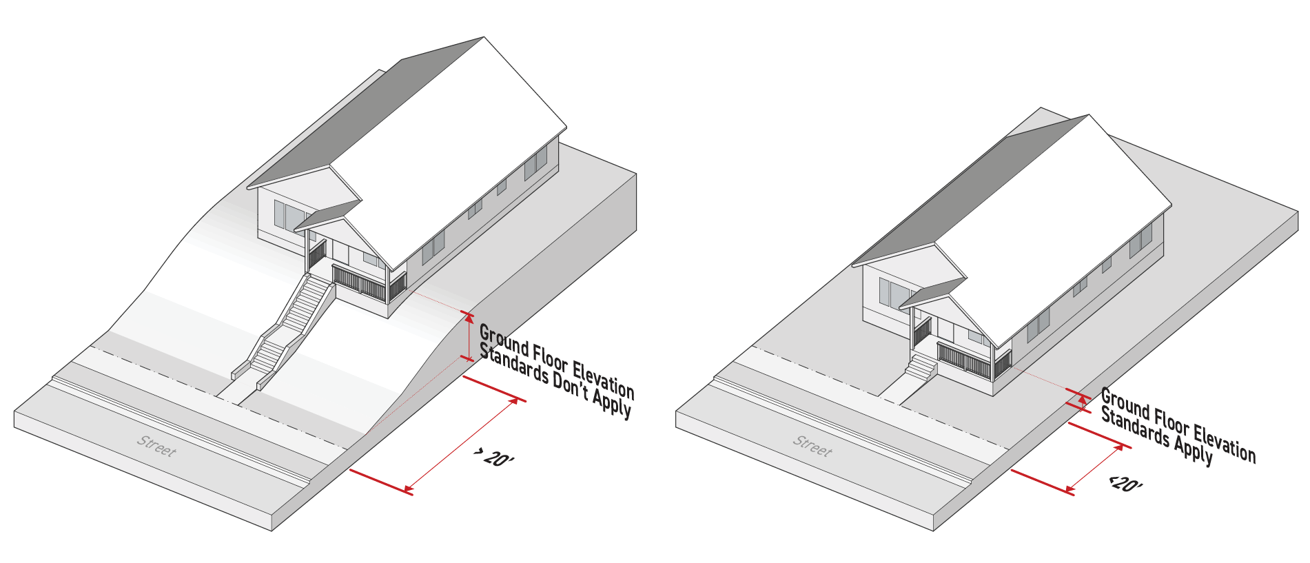
For structures located less than 20 feet from the frontage lot line, all portions of the ground story located within the first 15 feet of a frontage applicable facade pursuant to Sec. 3A.2.2.B.3. (Frontage Applicable Facades), measured inward and perpendicular to the frontage lot line, shall comply with ground floor elevation standards.
Standards
All occupiable space located in applicable portions of the ground story shall have a ground floor elevation no higher than the maximum ground floor elevation specified by the applied Frontage District (Part 3B.).
All occupiable space located in applicable portions of the ground story shall have a ground floor elevation no lower than the minimum ground floor elevation specified by the applied Frontage District (Part 3B.).
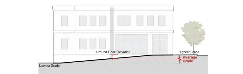
Measurement
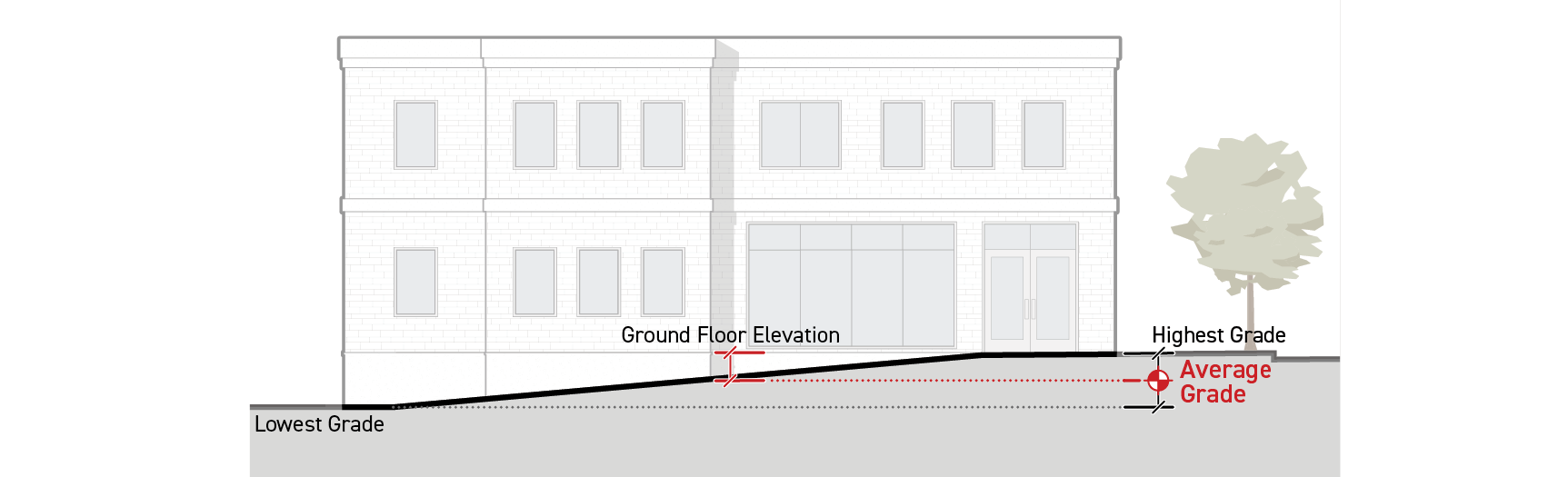
Where a building is located greater than 10 feet from a public sidewalk, ground story height is measured vertically from the average finished grade within five feet of the frontage lot line facing building perimeter to the finished floor elevation of the ground story.
Where a building is located 10 feet or less from a public sidewalk, ground floor elevation is measured vertically from the average sidewalk grade to the finished floor elevation of the ground story. Average sidewalk grade is measured as the average of the highest and lowest sidewalk elevation for the portion of the sidewalk located in front of the building.
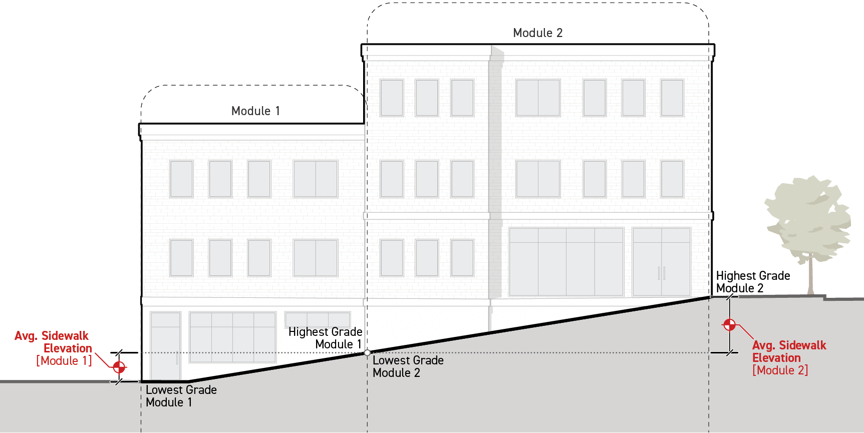
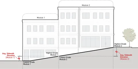
Ground floor elevation shall be measured independently for different modules of the building width. The ground floor elevation for each module shall be measured from either average sidewalk grade for the portion of the sidewalk in front of the module or from average finished grade within five feet of the frontage lot line facing building perimeter based on the distance of the building module from a public sidewalk according to Paragraph 1. and Paragraph 2. above.
For sloped lots, average elevation along the sidewalk shall be measured individually for each module and calculated as the average of the highest and lowest sidewalk elevation for the portion of the sidewalk located in front of the building module.
Exceptions
Ground floor elevation standards do not apply to structures located 20 feet or greater from the frontage lot line.
Relief
A deviation in minimum or maximum ground floor elevation up to 10 percent may be granted in accordance with Sec. 13B.5.2. (Adjustment).
Deviation from ground floor elevation standards may be granted as a variance in accordance with Sec. 13B.5.3. (Variance).