Use Finder
Part 3D. Character Frontage Rules
Div. 3D.1. Build-To
Div. 3D.2. Parking
See Div. 3C.2. (Parking).
Div. 3D.3. Landscaping
Div. 3D.4. Ground Floor Elevation
Div. 3D.5. Story Height
Sec. 3D.5.1. Ground Story Height
For the intent, applicability, standards, measurement, and relief of ground story height see Sec. 3C.6.1. (Ground Story Height).
Sec. 3D.5.2. Upper Story Height
Upper story height is defined as the floor-to-floor height of any story of a building located above the ground story.
Intent
The intent of the standards of this Section (Upper Story Height) is to ensure upper story spaces and their facades are scaled and proportioned to contribute to the established architectural character of surrounding neighborhoods or districts.
Applicability
Upper story height standards apply to new construction of multi-story buildings or structures. When upper story height standards apply, the standards apply to each story located above the ground story and all build-to applicable stories specified by the applied Frontage District (Part 3B.).
Standards
All occupiable space located in applicable portions of upper stories shall have a floor-to-floor height of no less than the upper story height minimum.
Measurement
Upper story height is measured vertically from the top of the finished floor to the top of the finished floor above.
Where no story exists above an upper story, upper story height is the shortest vertical distance from the top of the finished floor to the top of the ceiling or roof structure above.
Exceptions
Portions of upper stories located beyond the first 15 feet of a frontage applicable facade, measured inward and perpendicular to the facade are not required to meet upper story height standards.
Relief
A reduction in required upper story height of up to one foot may be granted in accordance with Sec. 13B.5.2. (Adjustment).
Deviations from upper story height standards may be granted as a variance in accordance with Sec. 13B.5.3. (Variance).
Div. 3D.6. Articulation
Sec. 3D.6.1. Base, Middle & Top Articulation
The base, middle & top articulation requirement is composed of three separate and coordinated articulating elements designed to visually break a building facade up into three separately legible layers.
Intent
The intent of the standards of this Section (Base, Middle & Top Articulation) is to visually break a building facade up into three separately legible building layers.
Applicability
Base, middle & top articulation standards apply to new construction or any exterior modification when the applied Character Frontage District (Div. 3B.9.) requires base, middle & top articulation on facades pursuant to Sec. 3A.2.2.B.3. (Frontage Applicable Facades).
Standards
General
One articulating element option shall be provided for each building layer in accordance with the building layer standards below.
Building Layers
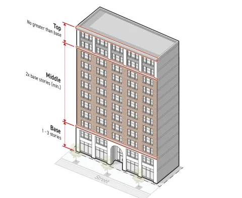
Base
The base building layer shall include at least one and no more than three contiguous stories starting with the ground story and continuing upward.
At least one of the following articulating elements shall be applied along the top of the base layer, creating a transition between the base and middle layers:
The articulating element shall extend for the full width of the building and be located no higher than the top of the uppermost story included in the layer.
Middle
The middle building layer shall include at least twice as many contiguous stories than the base building layer, starting at the top of the base layer and continuing upward.
At least one of the following articulating elements shall be applied along the top of the middle layer, creating a transition between the middle and top layers:
The articulating element shall extend for the full width of the building and be located no higher than the top of the uppermost story included in the layer.
Top
The top building layer shall include at least one story and shall not include more stories than the base building layer.
All stories located in the top building layer shall be contiguous and include, at minimum, all stories between the top of the middle layer and the top of the highest of the build-to applicable stories specified by the applied Frontage District (Part 3B.).
A roofline cornice articulating element shall be applied to the top building layer when the top building layer is the topmost story of the building or the topmost story before a street step-back. See Sec. 3D.6.5.C.4. (Roofline Cornice).
The roofline cornice shall extend for the full width of the building and be located along the top of the topmost story included in the building layer.
When the top building layer does not include the topmost story of the building or the topmost story before a street step-back, at least one of the following articulating elements shall be applied along the top of the top layer, creating a transition between the top building layer and any story above:
The articulating element shall extend for the full width of the building and be located along the top of the topmost story included in the building layer.
Measurement
For measurement of stories see Sec. 2C.4.3. (Height in Stories).
Exceptions
Where the applied Form District (Part 2B.) requires a street step-back depth of 10 feet or greater, the top building layer may terminate at the topmost story below the street step-back. No articulating element is required above the top building layer.
When a building is less than five stories, the standards of this Section (Base, Middle & Top Articulation) do not apply, and the standards of Sec. 3D.6.2. (Base-Top Articulation) apply.
Relief
Base, middle & top articulation standards may be met through alternative compliance in accordance with Sec. 13B.5.1. (Alternative Compliance).
A deviation from number of stories in building layers of one story may be granted in accordance with Sec. 13B.5.2. (Adjustment).
Deviation from any base, middle & top articulation standard may be granted as a variance in accordance with Sec. 13B.5.3. (Variance).

Sec. 3D.6.2. Base-Top Articulation
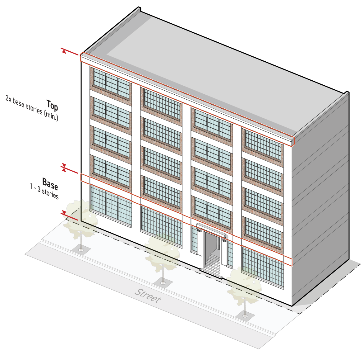
The base-top articulation requirement is composed of two separate and coordinated articulating elements designed to visually break a building facade up into two separately legible layers.
Intent
The intent of the standards of this Section (Base-Top Articulation) is to visually break a building facade up into two separately legible building layers.
Applicability
Base-top articulation standards apply to new construction and any exterior modification of a building or structure possessing five stories or fewer when the applied Character Frontage District (Div. 3B.9.) requires base-top articulation on all facades pursuant to Sec. 3A.2.2.B.3. (Frontage Applicable Facades).
Standards
General
One articulating element option shall be provided for each building layer in accordance with the building layer standards below. See Sec. 3D.6.5. (Articulating Elements).
Building Layers
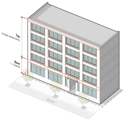
Base
The base building layer shall include between one and three contiguous stories starting with the ground story and continuing upward.
At least one of the following articulating elements shall be applied along the top of the base layer, creating a transition between the base and top layers:
The articulating element shall extend for the full width of the facade and be located no higher than the top of the uppermost story included in the layer.
Top
The top building layer shall include at least twice as many stories as the base building layer and include all remaining above-grade stories not included in the base building layer.
A roofline cornice articulating element shall be applied to the top building layer that is the topmost story of the building or the topmost story before a street step-back. See Sec. 3D.6.5.C.4. (Roofline Cornice).
The roofline cornice shall extend for the full width of the facade and be located along the top of the topmost story included in the building layer.
When the top building layer does not include the topmost story of the building or the topmost story before a street step-back, at least one of the following articulating elements shall be applied along the top of the top layer, creating a transition between the top building layer and any story above:
The articulating element shall extend for the full width of the building and be located along the top of the topmost story included in the building layer.
Measurement
For measurement of stories see Sec. 2C.4.3. (Height in Stories).
Exceptions
Where the applied Form District (Part 2B.) requires a street step-back depth of 10 feet or greater, the top building layer may terminate at the topmost story below the street step-back. No articulating element is required above the top building layer.
Relief
Base-top articulation standards may be met through alternative compliance in accordance with Sec. 13B.5.1. (Alternative Compliance).
A deviation from number of stories in building layers of one story may be granted in accordance with Sec. 13B.5.2. (Adjustment).
Deviation from any base-top articulation standard may be granted as a variance in accordance with Sec. 13B.5.3. (Variance).
Sec. 3D.6.3. Horizontal Band Articulation
Horizontal band articulation is a continuous band of material running horizontally across a facade.
Intent
The intent of the standards of this Section (Horizontal Band Articulation) is to separate and align windows on a building facade in a way that contributes to the established architectural character of surrounding neighborhoods or districts.
Applicability
Horizontal band articulation standards apply to new construction or an exterior modification when the applied Character Frontage District (Div. 3B.9.) requires horizontal band articulations on facades pursuant to Sec. 3A.2.2.B.3. (Frontage Applicable Facades).
Standards
Horizontal band articulation shall meet the following standards:
Be no less than eight inches in height,
Extend for the full width of the facade, interrupted only by required articulating elements or architectural features. Architectural features that interrupt either required vertical band articulation or required horizontal band articulation shall cover cumulatively no more than 30 percent of the total facade area. A maximum of five architectural features that interrupt required vertical band articulation or horizontal band articulation are allowed on the facade area of any individual building width.
Measurement
Horizontal band articulation height is measured vertically from the lowest point to the highest point of a horizontal band articulation meeting the standards above.
The facade area covered by an architectural feature that interrupts horizontal band articulation or vertical band articulation is measured as the area of the smallest rectangle that fully circumscribes the architectural feature.
Relief
Horizontal band articulation standards may be met through alternative compliance in accordance with Sec. 13B.5.1. (Alternative Compliance).
A deviation from horizontal band articulation dimensional standards up to 15 percent may be granted in accordance with Sec. 13B.5.2. (Adjustment).
Deviation from any horizontal band articulation standard may be granted as a variance in accordance with Sec. 13B.5.3. (Variance).
Sec. 3D.6.4. Vertical Band Articulation
Vertical band articulation is a continuous band of material running vertically up a facade.
Intent
The intent of the standards of this Section (Vertical Band Articulation) is to separate and align windows on a building facade in a way that contributes to the established architectural character of surrounding neighborhoods or districts.
Applicability
Vertical band articulation standards apply to new construction or an exterior modification when the applied CharacterFrontage District (Div 3B.9.) requires vertical band articulations on facades pursuant to Sec. 3A.2.2.B.3. (Frontage Applicable Facades).
Standards
Vertical band articulation shall meet the following standards:
Be no less than eight inches in width, and
Extend uninterrupted for the full height of all build-to applicable stories, only interrupted by horizontal band articulation, required articulating elements or architectural features. Architectural features that interrupt either required vertical band articulation or required horizontal band articulation shall cover cumulatively no more than 30 percent of the total facade area. A maximum of five architectural features that interrupt required vertical band articulation or required horizontal band articulation are allowed on the facade of any individual building width.
Spacing
Vertical band articulation shall be applied across the full width of a facade separated by no more than the maximum spacing and no less than the minimum spacing specified by the applied Frontage District (Part 3B.).
Vertical band articulation shall also be located at each corner of a building facade.
Measurement
Vertical band articulation width is measured parallel to the applicable facade and horizontally from one end of a vertical band meeting the standards above to the opposite end.
Vertical band articulation spacing is measured horizontally and perpendicular to the applicable building facade from edge of vertical band to edge of vertical band.
The facade area covered by an architectural feature that interrupts horizontal band articulation or vertical band articulation is measured as the area of the smallest rectangle that fully circumscribes the architectural feature.
Relief
Vertical band articulation standards may be met through alternative compliance in accordance with Sec. 13B.5.1. (Alternative Compliance).
A deviation from vertical band articulation dimensional standards up to 15 percent may be granted in accordance with Sec. 13B.5.2. (Adjustment).
Deviation from any vertical band articulation standard may be granted as a variance in accordance with Sec. 13B.5.3. (Variance).
Sec. 3D.6.5. Articulating Elements
Articulating elements are permanent architectural details used to embellish a facade design to accentuate an articulation technique or facade composition.
Intent
The intent of the standards of this Section (Articulating Elements) is to provide visual interest to the public realm and break up a building facade with visually separate building layers in a way that contributes to the established architectural character of surrounding neighborhoods or districts.
Applicability
Articulating element standards apply to new construction or an exterior modification when the applied Character Frontage District (Div. 3B.9.) requires articulating elements on facades pursuant to Sec. 3A.2.2.B.3 (Frontage Applicable Facades).
Articulating Element Options
Material Change
Standards
The principal exterior material applied to the building layer shall be different from the principal siding treatment applied to the abutting building layers.
The principal exterior material shall be limited to those allowed by the applied Frontage District (Part 3B.).
One of the following architectural details must be provided between building layers applying the material change articulating element:
A belt course located at the transition from one principal exterior material to the next. See Paragraph 2. (Belt Course) below; or
The building layer applying a material change articulating element shall be recessed or project from the abutting building layers at least three inches.
Measurement
In measuring material change, principal exterior materials are considered different if they are entirely different materials or products having the same base material where the unit size or finish surface texture is visibly contrasting.
Recessed building layers are measured horizontally from and perpendicular to the immediately surrounding facade to the outermost point of the recessed building layer facade.
Projecting building layers are measured horizontally and perpendicular from the immediately surrounding facade to the innermost point of the projecting building layer facade.
Belt Course
A horizontal course projecting beyond the face of the surrounding building facade often shaped to mark a division in the facade wall.
Standards
A belt course shall meet the following standards:
Extend uninterrupted for the full width of the building layer.
Have a consistent profile across the width of the building.
Project a minimum of two inches from the immediately surrounding facade for some portion of the top two inches and the bottom two inches of the belt course profile,
Have a height of no less than 12 inches if located on the first story. An additional two inches in height are required for each story that the belt course is located about the first story. The greatest required minimum height is 48 inches.
Measurement
Belt course height is measured vertically from the lowest point to the highest point of the belt course profile meeting the standards in subparagraph a above.
Projection is measured perpendicularly from the immediately surrounding facade to the outermost point of a belt course meeting the standards in the subparagraph a above.
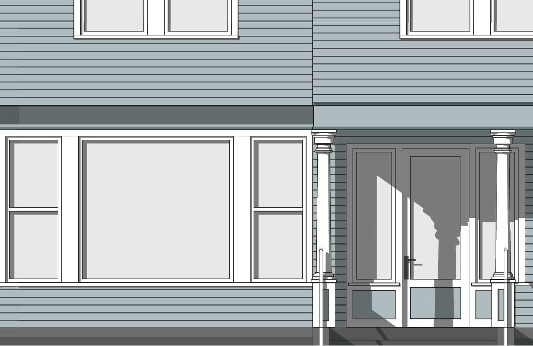
Shopfront Cornice
A continuous molded projection located above a series of display windows on the ground story facade.
Standards
A shopfront cornice shall meet the following standards:
Extend uninterrupted for the width of the building layer.
Project a minimum of four inches from the immediately surrounding facade for some portion of the top four inches and the bottom four inches of the cornice profile.
Have a height of no less than 12 inches.
Measurement
Shopfront cornice height is measured vertically from the lowest point to the highest point of the cornice profile meeting the standards in subparagraph a above.
Projection is measured perpendicularly from the immediately surrounding facade horizontally to the outermost point of a shopfront cornice meeting the standards in the subparagraph a above.
Roofline Cornice
A continuous molded projection that crowns a wall, often as part of a parapet.
Standards
A roofline cornice shall meet the following standards:
Extend uninterrupted for the full width of the building layer.
Project a minimum of four inches from the immediately surrounding facade for some portion of the top four inches of the cornice profile if located on the first, second or third stories. An additional two inches of projection are required for each story the roofline cornice is located above the third story. A minimum projection of at least 36 inches is required.
Have a height of no less than 12 inches if located on the first, second or third story. An additional two inches in height are required for each story the roofline cornice is located above the third story. A minimum height of at least 48 inches is required.
Measurement
Roofline cornice height is measured vertically from the lowest point to the highest point of the cornice profile meeting the standards above.
Projection is measured perpendicularly from the immediately surrounding facade horizontally to the outermost point of a roofline cornice meeting the standards in the subparagraph a above.
Measurement
Articulating elements are measured as "provided" or "not provided" based on whether the applicable building layer facade applies an articulating element meeting the standards above.
Relief
Articulating elements standards may be met through alternative compliance in accordance with Sec. 13B.5.1. (Alternative Compliance).
A deviation from articulating elements dimensional standards up to 10 percent may be granted in accordance with Sec. 13B.5.2. (Adjustment).
Deviation from any articulating elements standard may be granted as a variance in accordance with Sec. 13B.5.3. (Variance).
Div. 3D.7. Features
Sec. 3D.7.1. Restricted Features
Intent
The intent of the standards of this Section (Restricted Features) is to ensure facades are built in a way that contributes to the established architectural character of surrounding neighborhoods or districts by limiting the use of architectural features that are inappropriate to the historic or desired context.
Applicability
This Section (Restricted Features) applies to new construction or an exterior modification when the applied CharacterFrontage District (Part 3B.) restricts features on any facade pursuant to Sec. 3A.2.2.B.3. (Frontage Applicable Facades).
Standards
Where the applied Frontage District (Part 3B.) lists a feature as "prohibited", no applicable facade located on a build-to applicable story specified by the applied Frontage District (Part 3B.) may include any variety of listed feature.
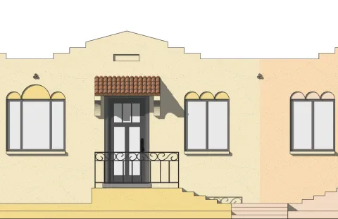
Projecting Balcony
An unenclosed occupiable platform, located at an elevation above the ground story, that is fixed to or integrated with an exterior building facade and projects beyond the floor area of the story immediately below. Balconies include protective barriers such as railings or parapets and may be covered or uncovered.
Standards
Where the applied Frontage District (Part 3B.) lists projecting balcony as "prohibited":
No feature meeting the definition for projecting balcony above may be included on an applicable facade.
Roof terraces that meet the definition of balcony may be allowed provided they are uncovered and do not project beyond the story immediately below.
Measurement
Projecting balconies are identified as present or absent based on whether an applicable facade includes a projecting balcony as described above.
Relief
Deviation from "restricted features" standards may be met through alternative compliance in accordance with Sec. 13B.5.1. (Alternative Compliance).
Deviation from any "restricted features" standards may be granted as a variance in accordance with Sec. 13B.5.3. (Variance).
Div. 3D.8. Entrances
Sec. 3D.8.1. Street-Facing Entrance
For the intent, applicability, standards, measurement, and relief of street-facing entrance see Sec. 3C.5.1. (Street-Facing Entrance).
Sec. 3D.8.2. Entry Feature
For the intent, applicability, standards, measurement, and relief of entry features see Sec. 3C.5.2. (Entry Feature).
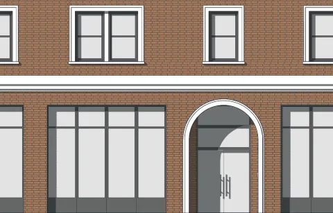
Sec. 3D.8.3. Focal Entry Feature
Focal entry feature are improved design standards applied to the primary entrance along the public realm.
Intent
The intent of the standards of this Section (Focal Entry Feature) is to establish a hierarchy of entrances on a building facade where a focal entry feature is the visually dominant entrance supported by secondary entrances designed with entry features.
Applicability
Focal entry feature standards apply to new construction, a major remodel, or an exterior modification, when the applied Character Frontage District (Part 3B.) requires a focal entry feature. When the focal entry feature standards apply, the focal entry feature standards apply to ground story, frontage lot line facing facades.
Standards
General
Each building width shall provide at least the minimum number of focal entry features specified by the applied Frontage District (Part 3B.).
Each required focal entry feature shall meet the standards for one of the focal entry feature options. See Sec. 3D.8.1.C.2. (Focal Entry Feature Options).
Required focal entry features shall abut and provide direct access to a street-facing entrance.
Required focal entry features shall provide direct access to the public realm associated with the frontage lot line.
For building setback encroachment regulations, see Sec. 2C.2.2.E. (Exceptions).
For encroachments into the public right-of-way, see Chapter IX. (Building Regulations), Sec. 91.32. (Encroachments into the Public Right-of-Way)of this Code.
Focal Entry Feature Options
Packages of design standards applied to the primary entrance along the public realm.
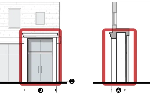
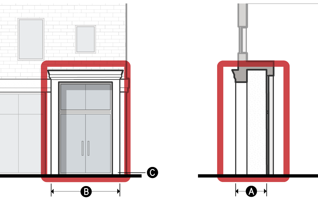
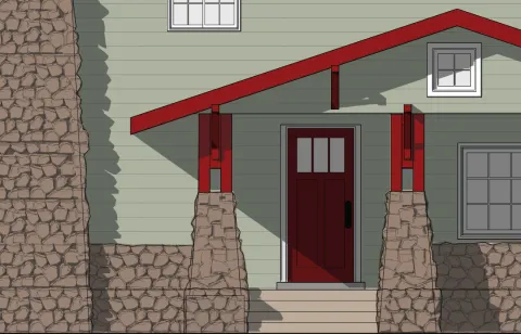
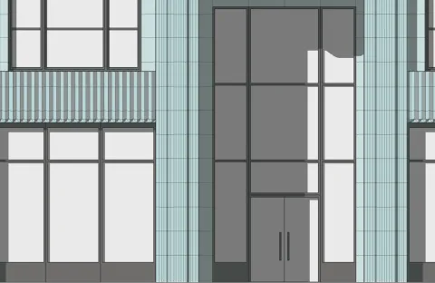
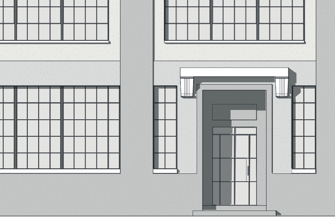
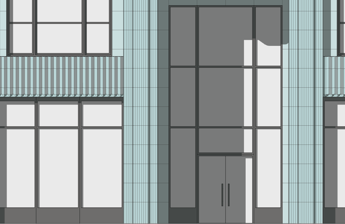
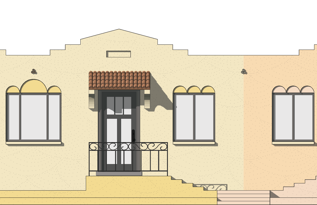
a.Archway
A curved symmetrical architectural detail spanning an opening to an exterior space, set behind the primary facade plane, providing sheltered access to a street-facing entrance.
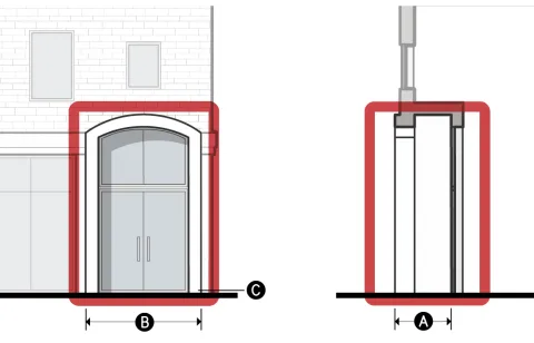
Dimensional Standards
For measurement see Sec. 3C.5.2.D.
A
Clear depth (min)
3'
B
Clear width (min)
8'
Clear height (min)
9'
Covered entrance
Required
Covered area (min)
100%
C
Finished floor elevation (min/max)
-2'/5'
Transparency (min)
80%
Enclosure (max)
75%
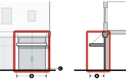
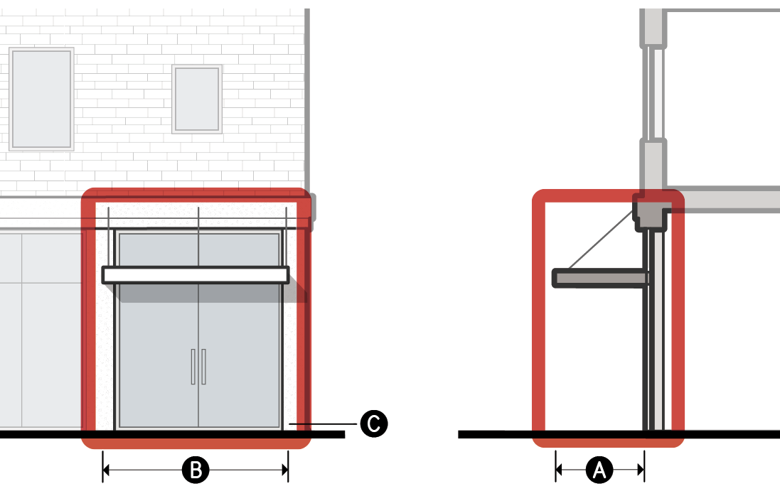
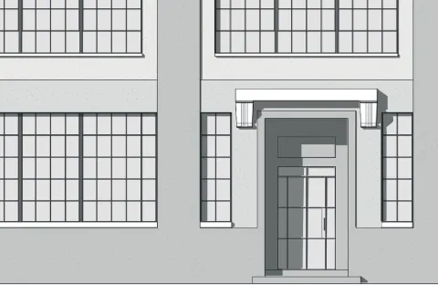
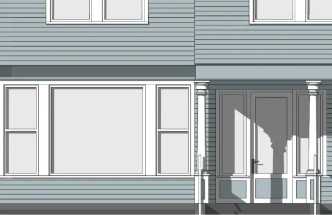
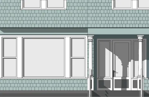
b.Architrave
A decorative horizontal band above and connected to vertical bands framing an opening to an exterior space, set behind the primary facade plane, providing sheltered access to a street-facing entrance.
Dimensional Standards
For measurement see Sec. 3C.5.2.D.
A
Clear depth (min)
3'
B
Clear width (min)
8'
Clear height (min)
9'
Covered entrance
Required
Covered area (min)
100%
C
Finished floor elevation (min/max)
-2'/5'
Transparency (min)
80%
Enclosure (max)
75%
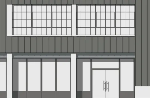
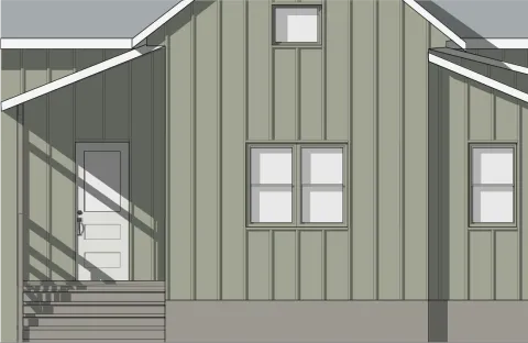
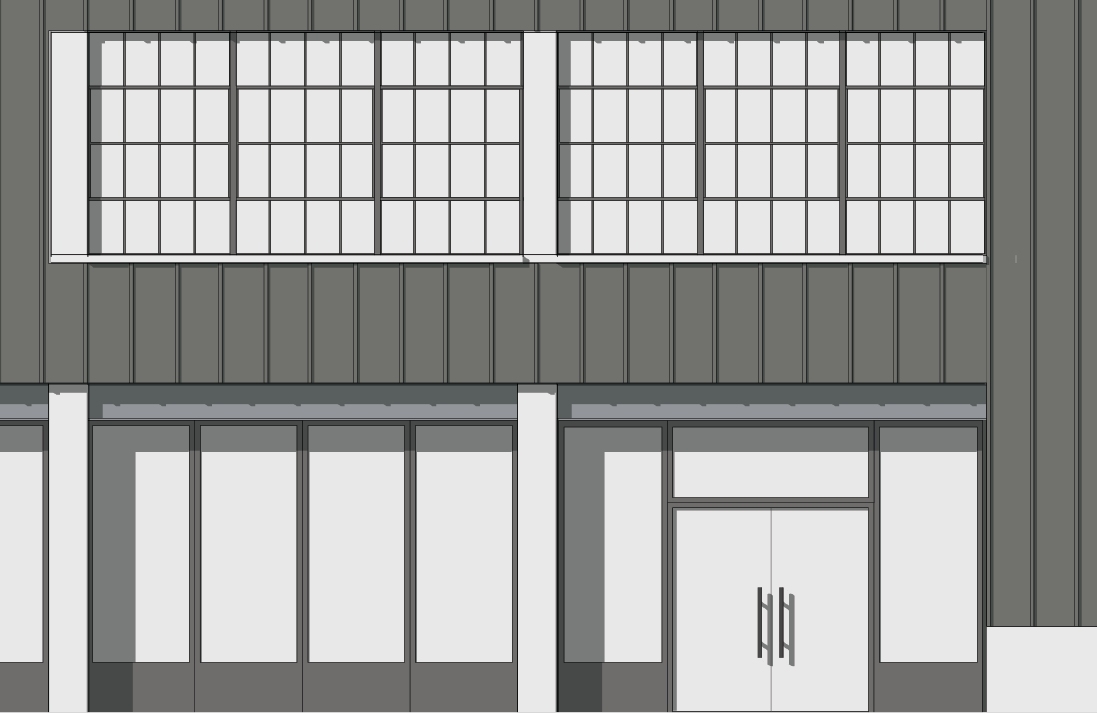
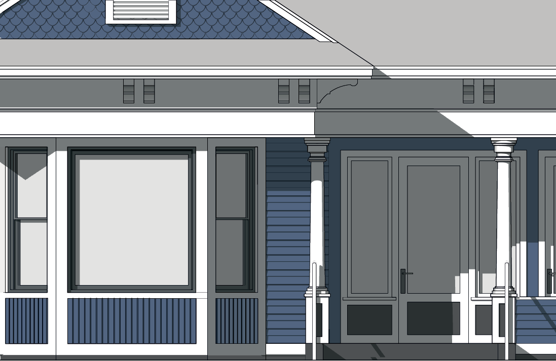
c.Canopy
A space that provides sheltered access to an at-grade street-facing entrance with an overhead projecting structure.
Dimensional Standards
For measurement see Sec. 3C.5.2.D.
A
Clear depth (min)
4'
B
Clear width (min)
8'
Clear height (min)
9'
Covered entrance
Required
Covered area (min)
n/a
C
Finished floor elevation (min/max)
-2'/2'
Transparency (min)
n/a
Enclosure (max)
50%
For encroachments into the public right-of-way, see Chapter IX. (Building Regulations), Sec. 91.32. (Encroachments into the Public Right-of-Way) of this Code.
Measurement
Relief
Deviation from focal entry feature option standards may be granted in accordance with Sec. 13B.5.1. (Alternative Compliance).
A deviation from focal entry feature dimensional standard up to 15 percent may be granted in accordance with Sec. 13B.5.2. (Adjustment).
Deviation from any entry feature standard may be granted as a variance in accordance with Sec. 13B.5.3. (Variance).

Div. 3D.9. Transparency
Sec. 3D.9.1. Ground Story
Intent
The intent of the standards of this Section (Ground Story) is to ensure projects are designed with ground story windows that contribute to the established architectural character of surrounding neighborhoods or district.
Applicability
Ground story transparency standards apply to new construction, a major remodel, or an exterior modification when the applied Character Frontage District (Div. 3B.9.) requires ground story transparency on facades pursuant to Sec. 3A.2.2.B.3. (Frontage Applicable Facades) located on the ground story and pursuant to Sec. 3A.2.2.B.4. (Frontage Applicable Building Depth).
Standards
General
Standards
Frontage applicable facades located on the ground story shall provide no less than the minimum transparency specified in the applied Character Frontage District (Div. 3B.9.).
Frontage applicable facades located on the ground story shall provide no more than the maximum transparency specified in the applied Character Frontage District (Div. 3B.9.).
All transparent area shall meet the standards of Sec. 3C.4.1.C. (Standards).
Measurement
For transparent area measurement, see Sec. 3C.4.1.D. (Measurement).
Active Wall Spacing
Window Recession
The depth that a window is set back from the surrounding facade.
Standards
All windows on applicable facades shall be recessed at a minimum depth as specified in the applied Frontage District (Part 3B.).
Measurement
Window recession depth is measured inward from the immediately surrounding facade surface, exclusive of trim or accessory projecting architectural details, to the outermost element of the window assembly.
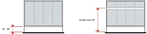
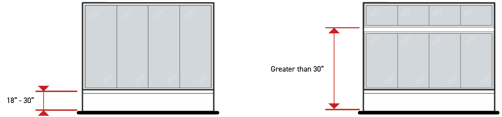
Bulkhead
A wall located beneath a display window on the ground story facade that elevates a window above the exterior finished grade and the interior finished floor surface.
Standards
When listed as "required" in the applied Frontage District (Part 3B.), all ground story window openings located on applicable facades shall be located between 18 and 30 inches above the finished floor of the ground story.
Ground story window openings located entirely above another ground story window may be located greater than 30 inches from the ground story finished floor provided that no portion of the opening extends beyond the width of the lower window opening.
Measurement
Bulkheads are measured as "provided" or "not provided" based on the compliance of all applicable windows with the standards above.
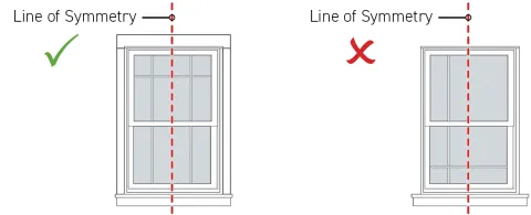
Symmetrical Lite Pattern
Window panes that are arranged or designed so that the left-side of the window composition is a mirror image of the right-side of the window composition.
Standards
When listed as “required" in the applied Frontage District (Part 3B.), all windows provided on applicable facades shall meet the following standards:
Divided-lite and simulated divided-lite windows shall have a composition of muntins or grills that display reflective symmetry.
Operable windows shall have sashes that are reflectively symmetrical.
Window assemblies sharing a window opening shall be composed in a way that reflective symmetry is displayed over the entirety of the window opening.
Measurement
In meeting symmetrical lite pattern standards, if a vertical line can be drawn through the window opening, and the pattern and shape on both sides of the line appear approximately identical, the window or windows are considered in compliance with the symmetrical lite pattern standard.
Horizontal Sliding Windows
Standards
When listed as "prohibited" in the applied Frontage District (Part 3B.), windows provided on applicable facades shall not include sashes that operate left to right or right to left.
Measurement
Horizontal sliding windows are identified as either present or absent.
Vinyl Windows
Standards
When listed as "prohibited" in the applied Frontage District (Part 3B.), window assemblies provided on applicable facades shall not contain frames, sashes, rails, styles, muntins, mullions, or grills with a vinyl exterior finish.
Other accessory window assembly components may be finished with vinyl products.
Measurement
Vinyl windows are identified as either present or absent.
Exceptions
Ground story transparency standards do not apply to parking structure facades unless the applied development standards district requires the facade to be wrapped, see Development Standards District (Part 4B.).
Relief
Up to a 15 percent increase to the total allowed ground story transparent area may be granted in accordance with Sec. 13B.5.2. (Adjustment).
A deviation from ground story transparency dimensional standard up to 15 percent may be granted in accordance with Sec. 13B.5.2. (Adjustment).
Deviation from any ground story transparency standard may be granted as a variance in accordance with Sec. 13B.5.3. (Variance).

Sec. 3D.9.2. Upper Stories
Intent
The intent of the standards of this Section (Upper Stories) is to ensure projects are designed with upper story windows that contribute to the established architectural character of surrounding neighborhoods or districts.
Applicability
Upper story standards apply to new construction, a major remodel, or an exterior modification when the applied Character Frontage District (Div. 3B.9.) requires upper story transparency on facades pursuant to Sec. 3A.2.2.B.3. (Frontage Applicable Facades) and Sec. 3A.2.2.B.4. (Frontage Applicable Building Depth).
Standards
General
Standards
Applicable upper story facades shall provide at least the minimum transparency specified in the applied Character Frontage District (Div. 3B.9.).
Applicable upper story facades shall provide no more than the maximum transparency specified in the applied Character Frontage District (Div. 3B.9.).
All transparent area shall meet the standards of Sec. 3C.4.1.C. (Standards).
Measurement
Window Recession
Symmetrical Lite Pattern
Sill
The bottommost horizontal exterior surface of a window opening including a ledge or other architectural detail that projects from the surrounding building facade.
Standards
When required by the applied Frontage District (Part 3B.), all windows provided on applicable facades shall include a sill, ledge or comparable architectural detail located at the bottommost exterior surface of a window opening.
Required sills shall project a minimum of one inch beyond the immediately surrounding building facade.
Required sills shall have a width of no less than the window opening.
Measurement
Sills are measured as "provided" or "not provided" based on the compliance of all applicable windows with the standards of subparagraph a above.
Horizontal Sliding Windows
Vinyl Windows
Exceptions
Upper story transparency standards do not apply to parking structure facades unless the applied Development Standards District (Part 4B.) requires the facade to be wrapped.
Relief
Up to a 15 percent increase in the total allowed upper story transparent area may be granted in accordance with Sec. 13B.5.2. (Adjustment).
A deviation up to 15 percent from upper story transparency dimensional standards may be granted in accordance with Sec. 13B.5.2. (Adjustment).
Deviation from any upper story transparency standard may be granted as a variance in accordance with Sec. 13B.5.3. (Variance).
Div. 3D.10. Exterior Materials
Sec. 3D.10.1. Principal Material Coverage
Principal material coverage is defined as the building products used as the primary exterior wall finish materials of the exterior building facade.
Intent
The intent of the standards of this Section (Principal Material Coverage) is to visually unify the facade with a dominant material and ensure that building facades are finished with materials that contribute to the established architectural character of surrounding neighborhoods or districts.
Applicability
Principal material coverage standards apply to new construction, a major remodel, or an exterior modification. When the principal material coverage standards apply, the standards apply to facades pursuant to Sec. 3A.2.2.B.3. (Frontage Applicable Facades) and any build-to applicable story as specified by the applied Character Frontage District (Div. 3B.9.), and any portion of the frontage applicable facade located above the last provided story where the number of stories provided for any building is less than the specified build-to applicable stories.
Standards
General
The total percentage of applicable facade area finished in a primary material shall be no less than the minimum principal material coverage specified by the applied Character Frontage District (Div. 3B.9.).
Only exterior material options specified by the applied Character Frontage District (Div. 3B.9.) may be used as a primary material.
Only one primary material may used to meet the principal material coverage standard.
Exterior Material Options
For exterior material options standards, see Sec. 3D.10.3. (Exterior Material Options).
Measurement
Principal material coverage is calculated for each building width separately.
The principal material coverage percentage is the facade area covered in a principal material divided by the total applicable facade area.
The principal material coverage is measured as compliant or non-compliant based on whether it meets the standards and definition of one of the allowed exterior material options specified by the applied Frontage District (Part 3B.).
Exceptions
Principal material coverage standards do not apply to windows nor door openings.
Relief
Up to a 10 percent reduction to the total required facade area finished in an allowed primary exterior material may be granted in accordance with Sec. 13B.5.2. (Adjustment).
Deviation from any principal material coverage standard may be granted as a variance in accordance with Sec. 13B.5.3. (Variance).
Sec. 3D.10.2. Accessory Material Coverage
Accessory material coverage is defined as the building products used as an exterior wall finish material to accent or support the principal material.
Intent
The intent of the standards of this Section (Accessory Material Coverage) is to visually unify the facade with a consistent material palette and ensure that building facades are finished with materials that contribute to the established architectural character of surrounding neighborhoods or districts.
Applicability
Accessory material coverage standards shall apply to new construction, a major remodel, or an exterior modification. When the accessory material coverage standards apply, the standards apply to any facade pursuant to Sec. 3A.2.2.B.3. (Frontage Applicable Facades) and any build-to applicable story as specified by the applied Character Frontage District (Div. 3.9.), and any portion of the frontage applicable facade located above the last provided story where the number of stories provided for any building is less than the specified build-to applicable stories.
All exterior materials cumulatively covering between five percent and 30 percent of the total applicable facade area are considered an accessory material and shall comply with all accessory material coverage, exterior material options, and number of accessory material standards.
Standards
General
The total percentage of applicable facade area finished in an accessory material shall not exceed the maximum accessory material coverage specified by the applied Character Frontage District (Div. 3B.9.).
Only exterior material options specified by the applied Character Frontage District (Div. 3B.9.) may be used as an accessory material.
Exterior Material Options
For exterior material options standards, see Sec. 3D.10.3. (Exterior Material Options).
Number of Accessory Materials
Individual accessory materials may not exceed the maximum number of accessory materials specified by the applied Character Frontage District (Div. 3B.9.).
Measurement
Accessory material coverage is calculated for each building width separately.
Accessory material coverage percentage is the facade area covered in the accessory material product divided by the total applicable facade area.
Accessory material coverage is measured as compliant or non-compliant based on whether it meets the standards and definition of one of the exterior material options specified by the applied Character Frontage District (Div. 3B.9.).
Exceptions
Accessory material coverage standards do not apply to windows nor door openings.
Relief
Up to a 10 percent increase in the total allowed facade area finished in a secondary exterior material may be granted in accordance with Sec. 13B.5.2. (Adjustment).
Deviation from any accessory material standard may be granted as a variance in accordance with Sec. 13B.5.3. (Variance).
Sec. 3D.10.3. Exterior Material Options
Exterior material options is defined as building products allowed for use as primary or accessory exterior wall finish material.
Intent
The intent of the standards of this Section is to ensure that building facades are finished with materials that contribute to the established architectural character of surrounding neighborhoods or districts.
Applicability
Exterior material options standards apply to all exterior materials provided and shall comply with principal material coverage or accessory material coverage standards as specified by the applied Character Frontage District (Div. 3B.9.).
Standards
General
Proposed principal and accessory materials shall meet all standards and definitions of one of the exterior material options specified by the applied Character Frontage District (Div. 3B.9.) to comply with principal material coverage and accessory material coverage standards.
Exterior Material Options
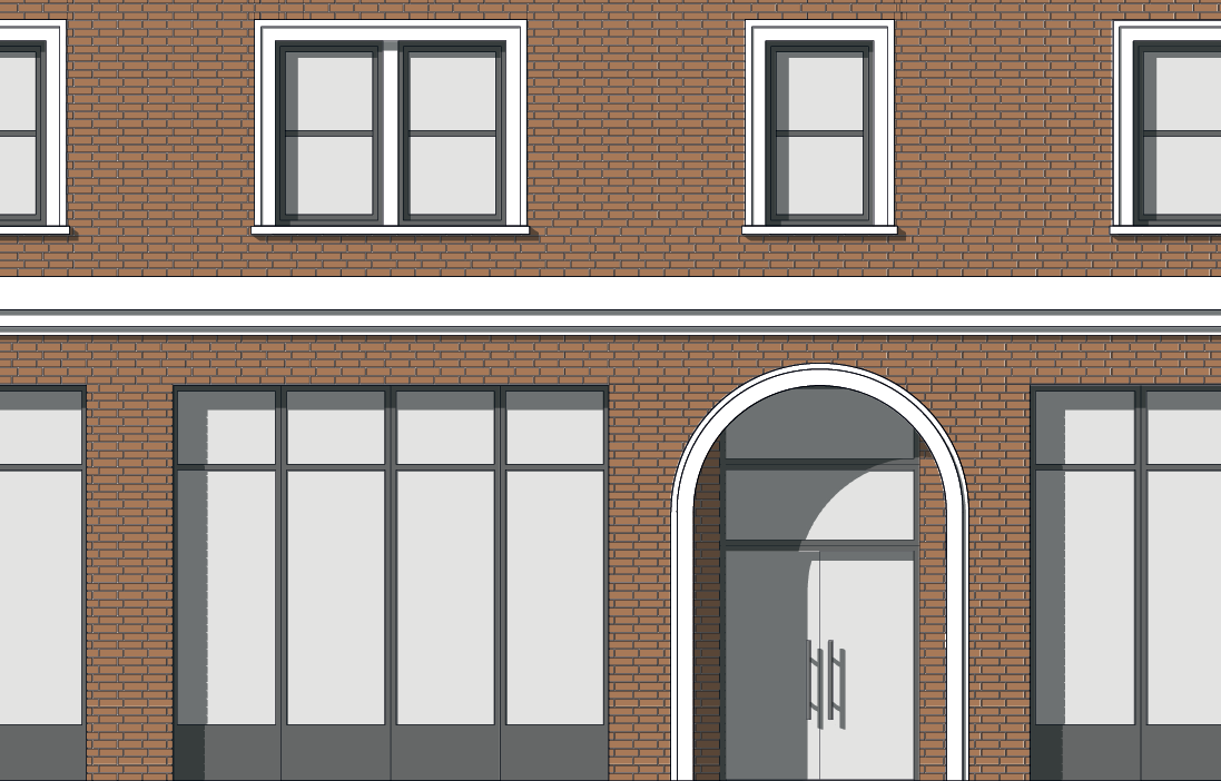
a.Brickwork
Courses of rectangular masonry units made of hardened clay, laid with mortar exposed between bricks. Examples include solid brick construction, brick veneer and thin brick veneer. Other products required for installation that are visually incidental to the brick are also included.
Intent
To provide structures with a human scale, durability, and a connection to local history. The profile of brickwork creates a pattern of channels along the mortar beds and perpends providing shadow line effects and texture reflecting the scale of the individual brick units. The size of the brick units are of a commonly recognized scale related to its manual assembly which naturally helps observers relate to the overall scale of the structure and recognize the building as a result of tangible human activities rather than machined or synthetic installations. Brick assemblies provide lasting durability against weather and wear, reducing maintenance demands. Used as an exterior building material in some of Los Angeles most treasured historic buildings, brickwork connects observers to local history.
Dimensional Standards
i.Individual brick units shall have a height of between 1.5 and 8 inches.
ii.Individual brick units shall have a width of between 3.5 and 16 inches.
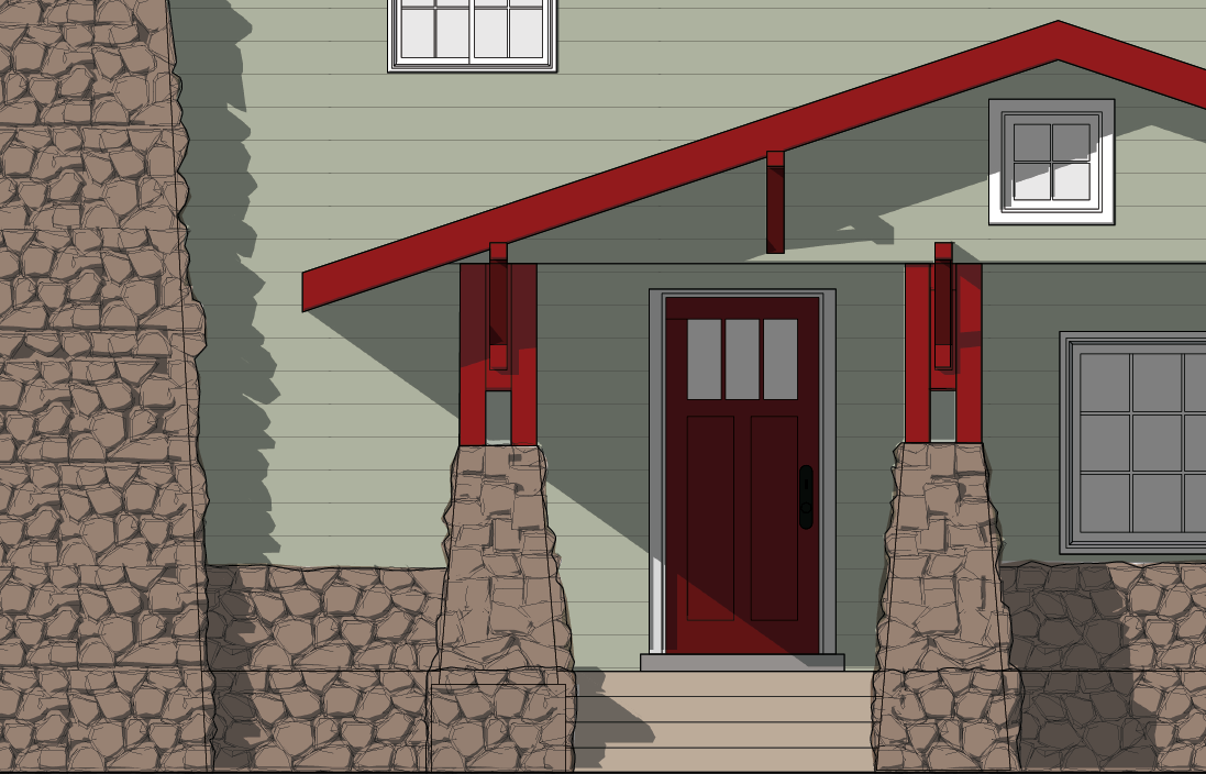
b.Stonework
Stacked rocks quarried and worked into a specific size and shape for use as a building material. Solid stone includes mortar and other products required for installation that are visually incidental to the stone product. Examples include solid stone construction, stone veneer, and thin stone veneer. Solid stone excludes heavy aggregate concrete, terrazzo, engineered stone products, and comparable materials.
Intent
To provide structures with a human scale, durability, and a connection to nature and local history. The profile of stonework provides dynamic shadow line effects relating to the scale of individual stones, helping observers to relate to the overall scale of the structure. The organic textures and deep natural colors of exposed stone faces provide observers with a connection to nature. Solid stone assemblies provide lasting durability against weather and wear, reducing maintenance demands. Used as an exterior building material in some of Los Angeles most treasured historic buildings, solid stone assemblies connect observers to local history.
Dimensional Standards
n/a
c.Concrete
A cement based product either poured-in-place or pre-cast in a form or mold. Concrete includes engineered masonry products set in resin or cement such as terrazzo, terracotta, CMU, breeze block, and exposed columns and beams. Other products required for installation that are visually incidental to the concrete product are also included. Concrete excludes fiber cement products, brick, EFIS, and stucco.
Intent
To provide structures with the lasting durability and a sense of weight and permanence through use of concrete.
Dimensional Standards
Not applicable
d.Metal
Metal products designed and intended for architectural purposes. Examples include exposed structural steel, architectural metal panels, and decorative metal products. Other products required for installation that are visually incidental to the metal product are also included.
Intent
To provide structures with the lasting durability and sense of permanence through use of metal.
Dimensional Standards
Not applicable
e.Wood
Tree-based products milled into a particular shape and size for use as an exterior building material. Examples include wood panels, structural lumber such as cross laminated timber and glulam beams, plank siding, and shingles. Wood excludes products with exposed faces composed substantially of wood chips, particles, and fibers. Examples include structural composite lumber like PSL, LSL, and OSL, and composite panel products like OSB, fiberboard, and particleboard. Wood also excludes faux-wood products such as vinyl, aluminum, and fiber cement siding. Other products required for installation that are visually incidental to the wood product are also included.
Intent
To provide structures with a connection to nature and local history through use of wood. The organic patterns and warm natural colors of exposed wood provide observers with a connection to nature. Used as an exterior building material in some of Los Angeles most treasured historic buildings, wood products connect observers to local history.
Dimensional Standards
Not applicable
f.Glazed Tile
Ceramic tile having porcelain or natural clay body, glazed for surfacing walls, typically attached to an exterior wall with mortar and finished by filling joints between tiles with a cement- or resin-based grout product. Examples include small or large format tile and structural facing tile. Other products required for installation that are visually subordinate to the tile product are also allowed. Glazed tile excludes terracotta and other non-ceramic tile products.
Intent
To provide structures with a human scale, durability, and a connection to local history. The profile of glazed tile assemblies provides a regular pattern of channels along grout joints, creating shadow line effects and texture reflecting the scale of the individual tile units. Glazed tile assemblies provide lasting durability against weather and wear, reducing maintenance demands. Used as an exterior building material in some of Los Angeles most treasured historic buildings, glazed tile assemblies connect observers to local history with their familiar luster and sheen.
Dimensional Standards
Not applicable
g.Horizontal Plank Siding
Courses of long, thin horizontal boards, often overlapping or interlocking horizontally but also including open joint systems. Horizontal plank siding includes clapboard, bevel, lap, weatherboard, shiplap, and rain screen siding and may be composed of a wide range of materials including wood, fiber cement products, and vinyl. Horizontal plank cladding excludes textured panel products with unit sizes exceeding 10 inches in height regardless of the pattern or texture.
Intent
To provide a human scale to buildings. The profile of the siding assembly creates a pattern of horizontal channels providing deep shadow line effects and texture reflecting the scale of the individual board units. The scale of the board units are of a commonly recognized scale related to its manual assembly which naturally helps observers to understand and relate to the overall scale of the structure and recognize the building as a result of tangible human activities rather than machined or synthetic installations.
Dimensional Standards
i.Individual board units shall have a height of between 2 and 10 inches.
ii.Overlapping or interlocking board units may have a height greater than 10 inches provided no board unit is exposed for a continuous height of more than 10 inches.
iii.Open joint systems shall not provide a gap greater than 3/4" between board units.
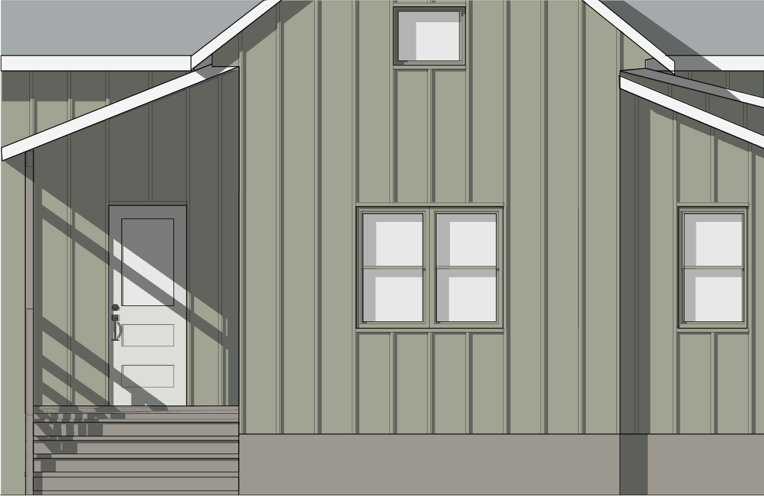
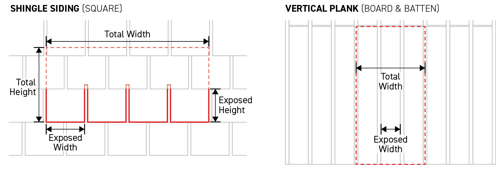
h.Vertical Plank Siding
Courses of long, thin vertical boards, often overlapping or interlocking vertically but also including open joint systems. Vertical plank siding includes, board and batten, tongue and groove, shiplap, and rain screen siding and may be composed of a wide range of materials including wood, fiber cement products, and vinyl. Vertical plank cladding excludes textured panel products with continuous reveal dimensions greater than 16 inches in width regardless of the pattern or texture.
Intent
To provide a human scale to buildings. The profile of the siding assembly creates a pattern of vertical channels providing deep shadow line effects and texture reflecting the scale of the individual board units. The scale of the board units are of a commonly recognized scale related to its manual assembly which naturally helps observers to understand and relate to the overall scale of the structure and recognize the building as a result of tangible human activities rather than machined or synthetic installations.
Dimensional Standards
i.Individual board units shall have a width of between 1 and 16 inches.
ii.Overlapping or interlocking board units may have a width greater than 16 inches provided no board unit is exposed for a continuous width of more than 16 inches.
iii.Open joint systems shall not provide a gap greater than 3/4" between board units.
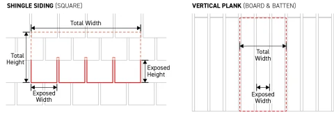
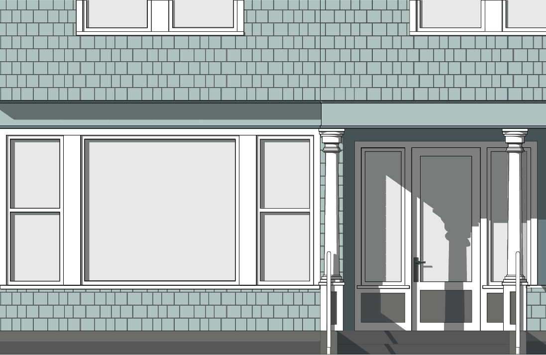
i.Shingle Siding
Courses of short, thin building materials, overlapping horizontally. Shingle siding includes square, round, half-cove, and hexagon, shaped shingles and be composed of a wide range of materials including cedar, cementitious fiberboard, and vinyl. Shingle siding excludes asphalt roofing shingles and textured panel products with continuous reveal dimensions greater than 24 inches in width or 12 inches in height regardless of the pattern or texture.
Intent
To provide a human scale to buildings. The profile of the shingle assembly creates a pattern of vertical and horizontal channels providing deep shadow line effects and texture reflecting the scale of the individual shingle units. The scale of the shingle units are of a commonly recognized scale related to its manual assembly which naturally helps observers to understand and relate to the overall scale of the structure and recognize the building as a result of tangible human activities rather than machined or synthetic installations.
Dimensional Standards
i.Individual shingle units shall have a width of between 2 and 24 inches.
ii.Individual shingle units shall have a height of between 2 and 12 inches.
iii.Shingle units may have a width greater than 24 inches or a height greater than 12 inches provided no individual shingle is exposed for a continuous width of more than 24 inches or a continuous height of more than 12 inches.
j.Stucco
A building material composed primarily of Portland cement, finely ground limestone, sand and water, applied directly onto a building over a reinforcing base mesh. Stucco excludes textured panel products and synthetic stucco such as EIFS, elastomeric stucco, and acrylic stucco.
Intent
To provide structures with durability and a connection local history. Stucco provides lasting durability against weather and wear, reducing maintenance demands. Used as an exterior building material in some of Los Angeles most treasured historic buildings, stucco connects observers to local history.
Dimensional Standards
Not applicable
Measurement
The height of individual board, brick, or shingle unit is measured as the greatest dimension from one end of the unit to the opposite end of the unit, measured vertically and based on the proposed installation pattern.
The width of individual board, brick, or shingle unit is measured as the greatest dimension from one end of the unit to the opposite end of the unit, measured horizontally and based on the proposed installation pattern.
Exposed width is measured as the largest horizontal dimension of a board or shingle unit that is uninterrupted by either, another board or shingle covering the first unit, or a gap or break in the board or shingle unit, for the full height of the unit.
Exposed height is measured as the largest vertical dimension of a board or shingle unit that is uninterrupted by either, another board or shingle covering the first unit, or a gap or break in the board or shingle unit, for the full height of the unit.
Gap between board units is measured as the distance between board units at the widest point.
Relief
Deviation from exterior material option standards may be granted in accordance with Sec. 13B.5.1. (Alternative Compliance).
Up to a 10 percent modification to any exterior material option dimensional standard may be granted in accordance with Sec. 13B.5.2. (Adjustment).
Deviation from any exterior material option standard may be granted as a variance in accordance with Sec. 13B.5.3. (Variance).
Div. 3D.11. Roof Design
Sec. 3D.11.1. Roof Form
Roof form is defined as the shape of the external upper covering of a building, including the frame for supporting the roofing.
Intent
The intent of the standards of this Section (Roof Design) is to ensure that building forms contribute to the established architectural character of surrounding neighborhoods or districts.
Applicability
Roof form standards apply to new construction, a major remodel, or an exterior modification when the applied Character Frontage District (Div. 3B.9.) requires a primary roof form on any frontage lot line-facing buildings.
A minimum of 70 percent of the total roof area of each applicable building or structure shall meet roof form standards, measured horizontally.
Standards
General
All building and structures shall have a roof form listed as a roof form option in the applied Frontage District (Part 3B.).
Roof Form Options
Flat
A roof with a maximum pitch of 2:12 (two inch of vertical rise for every 12 inches of horizontal span) or less. Flat roof forms include roofs with parapets up to six feet in height.
Measurement
Roof pitch is measured by calculating a roof's vertical rise in inches divided by a foot of its horizontal span and is represented as a ratio.
Roof form is measured as compliant or non-compliant based on whether it meets the standards and definition of one of the roof form options allowed by the applied Frontage District (Part 3B.).
Relief
Up to a 10 percent reduction in the total required roof area having an allowed roof form may be granted in accordance with Sec. 13B.5.2. (Adjustment).
A deviation from roof form dimensional standard up to 10 percent may be granted in accordance with Sec. 13B.5.2. (Adjustment).
Deviation from any roof form standard may be granted as a variance in accordance with Sec. 13B.5.3. (Variance).
Sec. 3D.11.2. Roof Materials
Intent
The intent of the standards of this Section (Roof Materials) is to ensure that a building's roof finishing materials contribute to the established architectural character of surrounding neighborhoods or districts.
Applicability
This Section (Roof Materials) applies to new construction, a major remodel, or an exterior modification. When roof materials standards apply, the standards apply to all portions of a required primary roof form pursuant to Sec. 3D.11.1. (Roof Form) on any frontage lot line-facing buildings on a lot.
Standards
Only roof materials specified by the applied Frontage District (Part 3B.) shall be used to finish an applicable roof.
Measurement
Roof materials are measured as compliant or non-compliant based on whether all applicable roofs meet the roof materials standards.
Exceptions
Roof material standards do not apply to accessory roof forms.
Relief
Up to a 10 percent reduction in the total required roof area finished of an allowed roof material may be granted in accordance with Sec. 13B.5.2. (Adjustment).
Deviation from roof materials standards may be granted as a variance in accordance with Sec. 13B.5.3. (Variance).